Mutual coupling based calibration technique for structurally deformed phased array apertures

Active Publication Date: 2014-09-23
THE GOVERNMENT OF THE UNITED STATES OF AMERICA AS REPRESENTED BY SEC OF THE NAVY
View PDF7 Cites 14 Cited by
  • Summary
  • Abstract
  • Description
  • Claims
  • Application Information

AI Technical Summary

Benefits of technology

[0011]The advantages of this technique lie in its ability to provide in situ calibration without the requirement for external calibration sources. The invention uses mutual coupling between

Problems solved by technology

However, the ship structure can deform due to mechanical and thermal stresses and these stresses can significantly degrade the antenna radiation pattern.
Unlike integrated (no cut-out) designs, which are able to maintain structural continuity, the cut-out design suffers from structural inefficiencies such as lack of stiffness, vibrati

Method used


Image

  • Mutual coupling based calibration technique for structurally deformed phased array apertures
  • Mutual coupling based calibration technique for structurally deformed phased array apertures
  • Mutual coupling based calibration technique for structurally deformed phased array apertures

Examples


Embodiment Construction

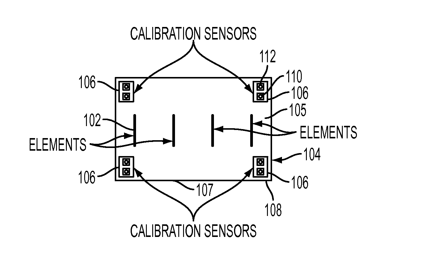
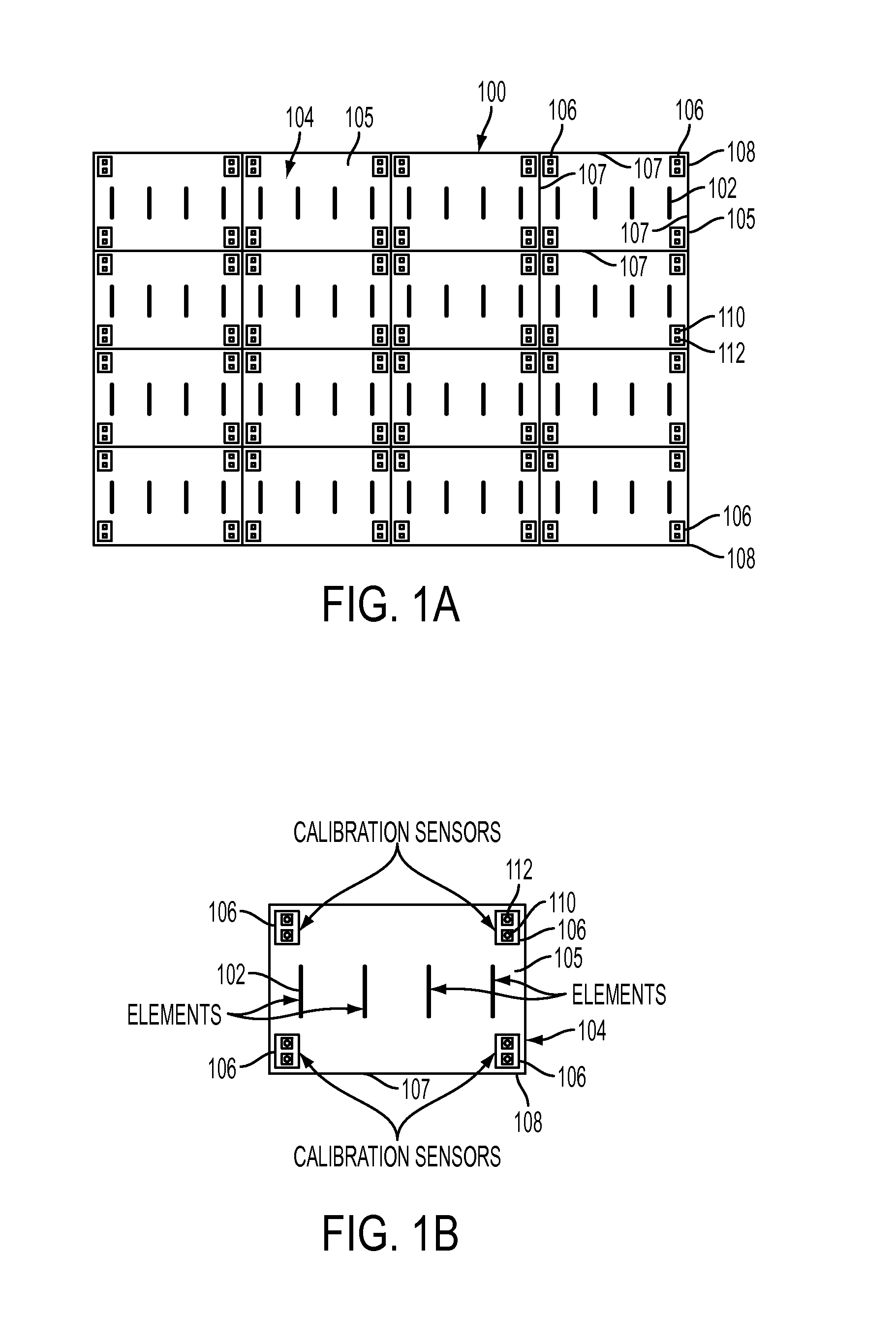
[0014]Large antenna arrays are often constructed modularly in order to simplify transportation and installation of the array. The individual panels of a modular antenna array are referred to as subarrays. In many applications, the subarray panels are required to serve as structural members of the overall array. Therefore, the subarray panels are subjected to mechanical and thermal stresses that can alter the subarray shape and location. Deformation of the subarray configuration results in changes to the pointing angle and physical location of each array element. Subsequently, the performance of the antenna array is degraded.

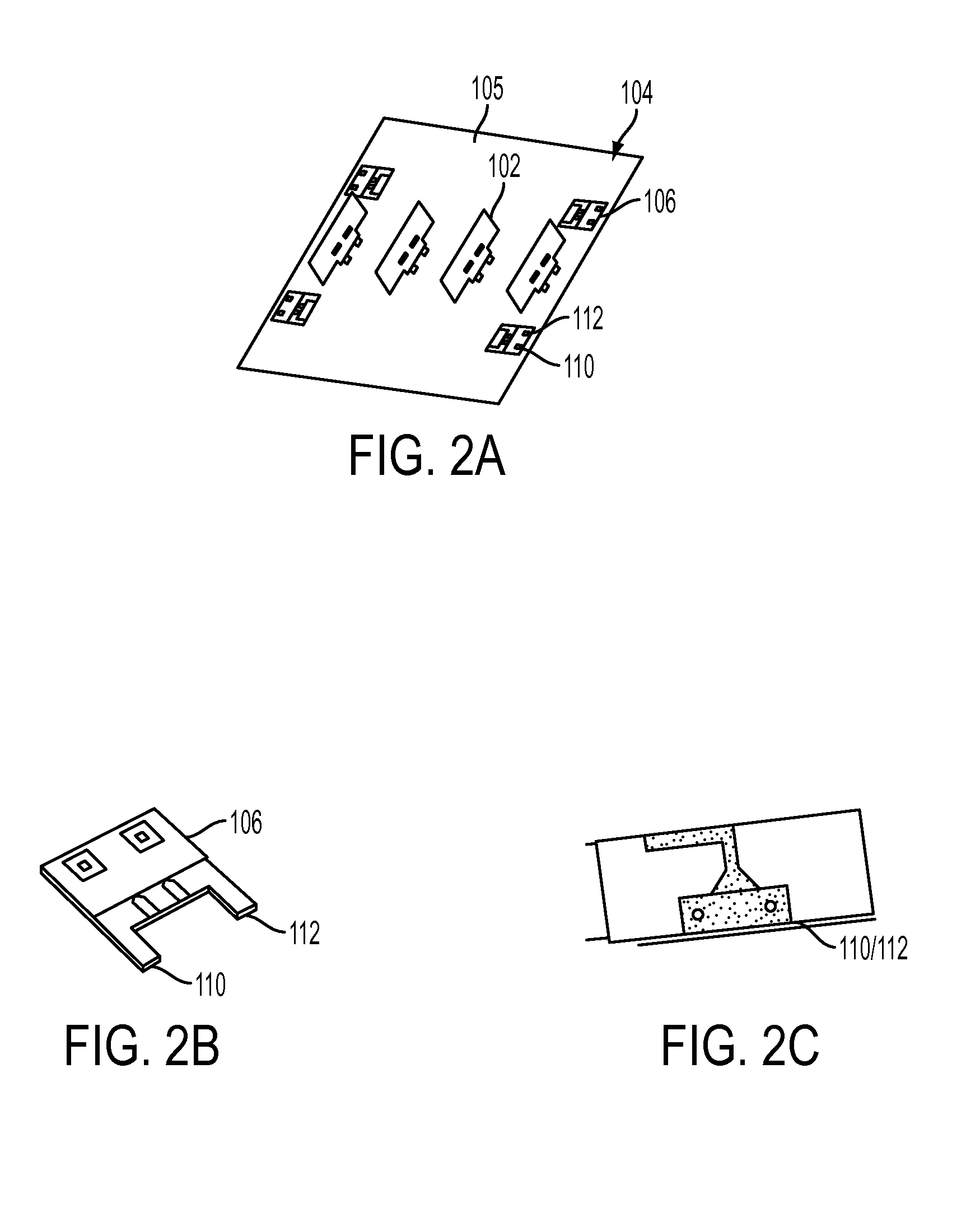
[0015]The complex excitation of the elements within the antenna array can be altered to optimize the performance of the deformed antenna array. The disclosed calibration methodology correlates the changes in the mutual coupling of sensor antennas to physical changes in aperture shape. Once the physical deformations are understood, the proper complex element excit...


PUM


Abstract

A phased array antenna includes a plurality of subarrays, and each subarray includes a panel, a plurality of primary antenna elements positioned on the panel, and at least one pair of sensor antenna elements positioned along a perimeter of the panel. One of the sensor antenna elements is a transmitting sensor antenna element and the other sensor antenna element is a receiving sensor antenna element. Changes in the mutual coupling between the two high frequency sensor antenna elements as a function of deformation of the subarrays provides a calibration signal outside of the operational band of the array while the array is operated and without requiring external calibration sources.

Description

CROSS-REFERENCE TO RELATED APPLICATIONS[0001]This Application claims the benefit of U.S. Provisional Application 61 / 355,720 filed on Jun. 17, 2010 and incorporated herein by reference.FIELD OF THE INVENTION[0002]The present invention is directed to a radar array calibration system and method, and more particularly to the calibration of a modular phased array consisting of multiple subarrays.BACKGROUND OF THE INVENTION[0003]Phased array antennas on future Navy ships may be embedded directly onto the ship's structure. By embedding the antennas directly into the ship's structure, it will be possible to make full use of available space on the body of the ship and free up critical space on the ship deck for other critical radars necessary for increasing Navy requirements. However, the ship structure can deform due to mechanical and thermal stresses and these stresses can significantly degrade the antenna radiation pattern.[0004]Ships like DDG-1000, CG(X) and DDG(X) are going to have a la...

Claims


Application Information

Patent Timeline
IPC IPC(8): G01S7/40H01Q3/26
CPCH01Q3/267G01S7/4021G01S7/4026H01Q21/24H01Q3/2629H01Q21/0025H01Q21/28G01S2013/0245
Inventor DORSEY, W MARKMITAL, RASHMIPARENT, MARK GTAYLOR, DOUG
Owner THE GOVERNMENT OF THE UNITED STATES OF AMERICA AS REPRESENTED BY SEC OF THE NAVY
Why Eureka
Try Eureka