Double stacked projection

a projection and double stacked technology, applied in the field of double stacked projection, can solve the problems of difficult alignment of double stacked projectors, lack of brightness, and difficulty in traditional double stacking at such high resolutions, and achieve the effect of high quality

Active Publication Date: 2014-09-23
IMAX THEATERS INT
View PDF60 Cites 20 Cited by
  • Summary
  • Abstract
  • Description
  • Claims
  • Application Information

AI Technical Summary

Benefits of technology

[0103]A first advantage of the invention is that the smoother image of the second projector 2 reduces the visible artefacts introduced by a smaller misalignment of the projected images. In many cases, a misalignment of a full pixel or more is not noticeable, which in a traditional double stacking configuration would have introduced highly visible artefacts.
[0104]However, as can be seen on the first graph in FIG. 6, the output of the second constrained smoothing filter 15 is not completely eliminated high frequency components. At high contrast edges in the source image where the contrast is close to or above the contrast reproduction capability of the first projector 1, the upper bound and lower bound inputs to the first constrained smoothing filter 14 get so close, so it may not always be possible to create a smooth “curve” (or rather: surface) between them, and these areas of the projected image will be the most sensitive to misalignment. Setting r2 to a value higher than 0 will enforce a smoothing also in these areas, reducing spatial frequency components further and increase the misalignment tolerance. The cost of this increased misalignment tolerance is losing the ability of achieving “perfect reconstruction” and introducing small artefacts even at perfect alignment of the projected images, in the form of faint haloes around edges in the source image with a contrast higher than the first projector 1 is capable of reproducing. Hence, adjusting r2 defines a compromise between “perfect reconstruction” and “high misalignment tolerance”.
[0105]FIG. 7 is equivalent to FIG. 6, except that the dilation radius r2 is 2 pixels here and the blur radius r2′ is essentially equal to r2. The dilation radius r1 is still 3 pixels and the blur radius r1′ is still essentially equal to r1. The faint halo artefact is visible in the summed graph at the bottom just to the left of the highest peak. Fortunately, these artefacts may be unrecognizable for the Human Visual System in a projected image due to lateral inhibition in the neural response system on the retina (lateral masking), when r2 is below a limit determined by the overall projection system on-screen contrast, hence theoretical “perfect reconstruction” is not necessarily needed. Determining a good value for r2 for a given type of projection system may be performed by having a critical group of observers located in the front rows look at a test pattern containing maximum contrast edges and switch between random values of r2 and ask the group members to rate the images in terms of edge sharpness and then selecting the value of r2 where nobody notices the reduction of edge sharpness. It is noted that the reason for selecting the second constrained smoothing filter 15 also for the second filtering pass, as opposed to for example selecting a standard lowpass filter, is that this configuration preserves illumination intensity in small areas of highlights like reflections in water or leafs, which may be important visual clues that are not subject to suppression by lateral inhibition.
[0106]FIG. 8 shows printed images of an output of the second constrained smoothing filter 15 together with the output of the image subtraction circuit 13 and a simulation of the resulting projected overlaid image calculated by adding the output of the second constrained smoothing filter 15 and the output of the image subtraction circuit 13. (The images have here been applied a gamma so they are watchable on print).

Problems solved by technology

Modern super high resolution 4K digital cinema projectors designed for normal sized cinema screens have a resolution ideal also for very large screens but lack the brightness needed for these.
Double stacking projectors are an effective way of increasing brightness, but traditional double stacking is difficult at such high resolutions because the tolerance in the alignment of projected images becomes very small and is hard to meet during presentations due to thermal induced movements in the mechanical and optical parts and vibrations from the audio system.
In other applications like temporary projection set-ups, home cinemas etc., alignment of double stacked projectors may be difficult to maintain even when working at much lower resolutions.
However, it is also well known that traditional double stacking requires high maintenance of the alignment of the projectors to maintain image quality.
In 4K projection, traditional double stacking is not considered an option, because it would be impossible to keep the sharpness and detail on par with that of a single 4K projector throughout a presentation.
This is unfortunate for giant screen theatres, because while 4K projectors lend themselves well to giant screens in terms of resolution, available projectors generally do not have enough light for giant screens, so stacking would seem desirable to double the light output.

Method used


Image

  • Double stacked projection
  • Double stacked projection
  • Double stacked projection

Examples


Embodiment Construction

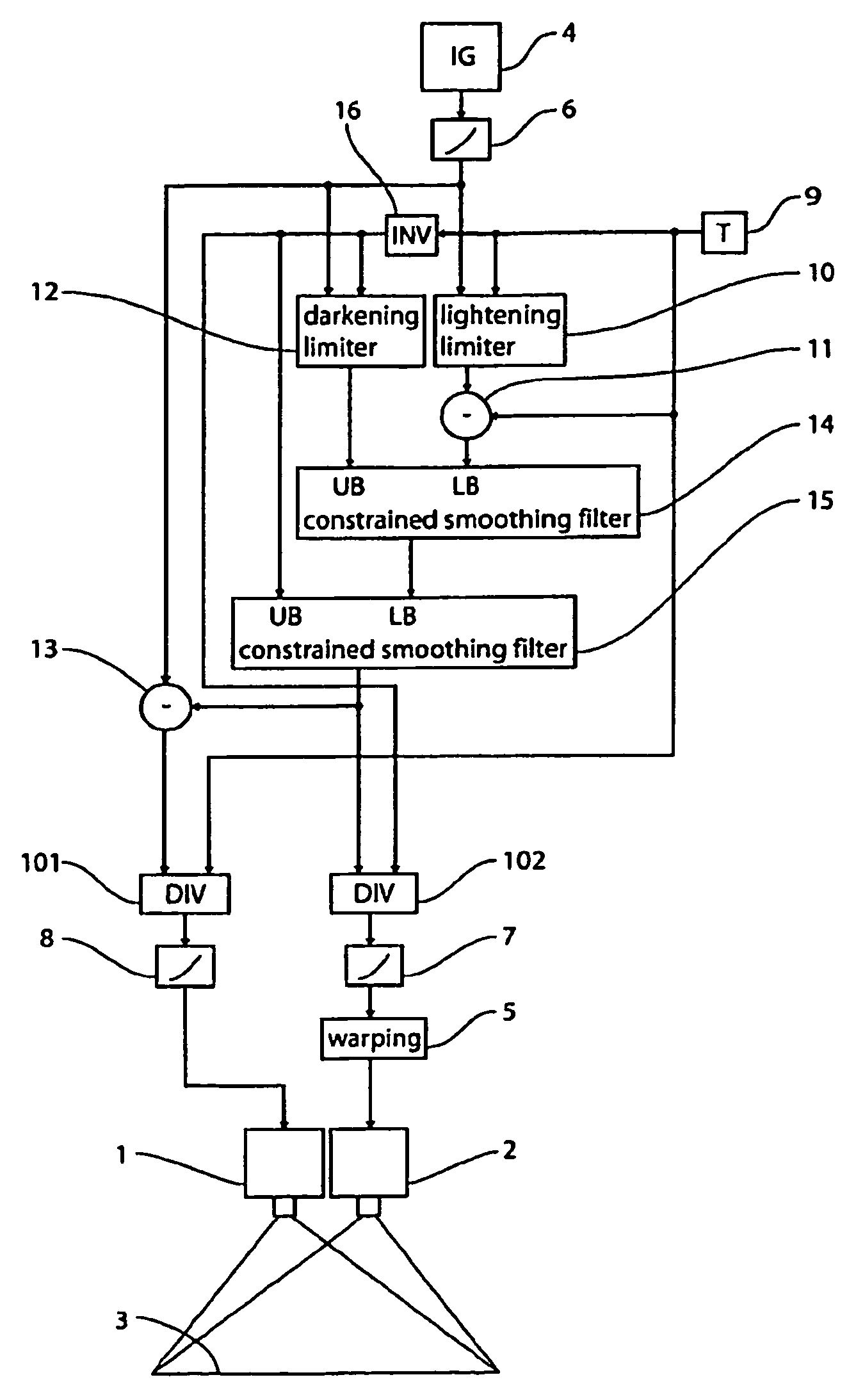
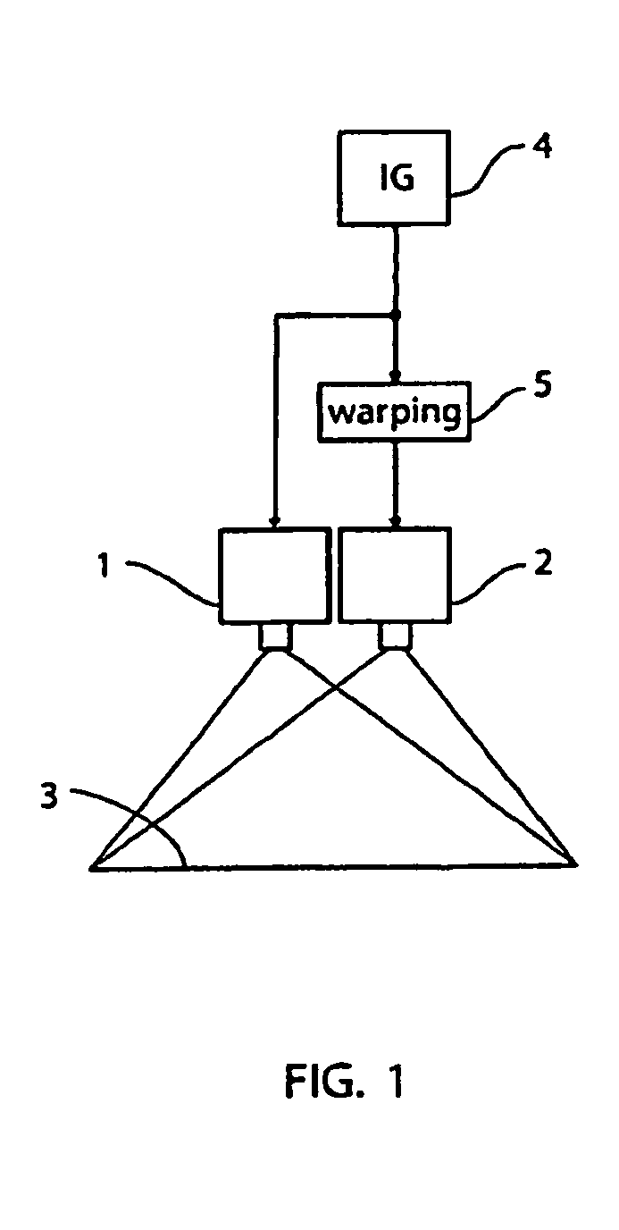
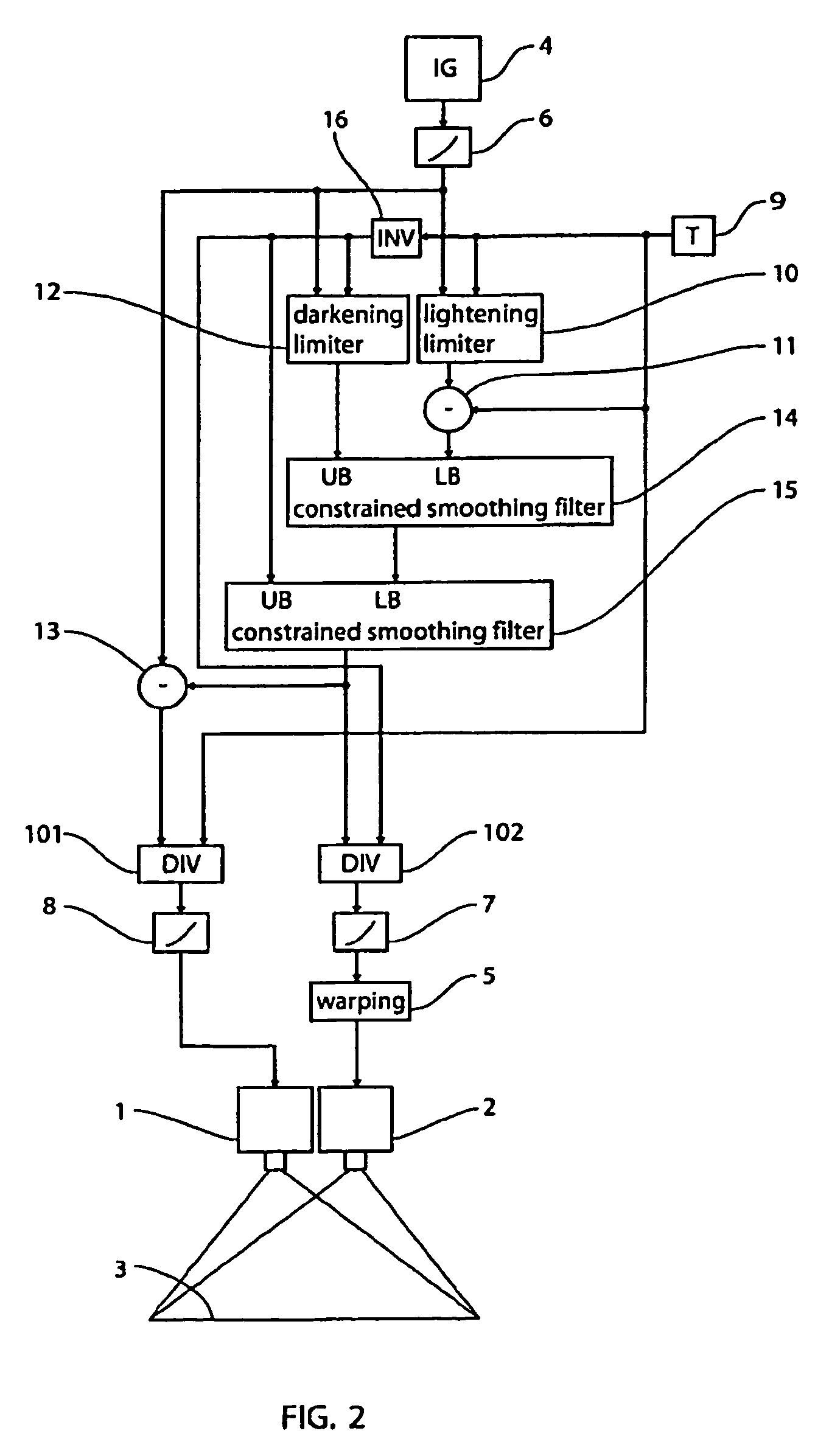
[0086]The present invention is described below in terms of exemplary configurations but is not intended to be regarded as limited to those. For the sake of explanation, greyscale projection systems are used to describe the present invention, whereas the configurations described may as well be applied to each of the colour planes of a tri-stimulus (for example RGB) colour projection system, and, using standard colour space conversion techniques, further be used for projection systems using other colour spaces (for example YPbPr). Further, colour correction circuits for adapting for example hue adjustment, black points and white points etc. between source image signals and projectors may obviously be included. Still, image projection systems are used in several descriptions, whereas the described configurations may as well operate on a sequence of still images constituting a moving image. Monoscopic projection systems are used in the description, but the invention may as well apply to...


PUM


Abstract

A method for producing a first output image and a second output image for being projected by a first projector and a second projector, respectively, is disclosed. The method comprises: providing a source image comprising a plurality of pixels, each pixel having a source value, providing an inverted threshold value for each pixel of the plurality of pixels, and generating thereof a temporary image comprising a temporary value for each pixel of the plurality of pixels. The method further comprises: generating the first output image comprising a first output value for each pixel of the plurality of pixels, the first output value being generated from the temporary value and the source value for each pixel, and generating the second output image comprising a second output value for each pixel of the plurality of pixels, the second output value being generated from the temporary value.

Description

CROSS-REFERENCE TO RELATED APPLICATIONS[0001]This is a U.S. national phase under 35 U.S.C. 371 of International Patent Application No. PCT / EP2011 / 056173, entitled “Double Stacked Projection” and filed Apr. 18, 2011, which claims benefit of priority under PCT Article 8 of Danish Application No. PA 201000320 filed Apr. 18, 2010, Danish Application No. PA 201000321 filed Apr. 18, 2010, and U.S. Provisional Application No. 61 / 356,980 filed Jun. 21, 2010. Each and every application is incorporated herein by reference in its entirety.BACKGROUND OF THE INVENTION[0002]Modern super high resolution 4K digital cinema projectors designed for normal sized cinema screens have a resolution ideal also for very large screens but lack the brightness needed for these. Double stacking projectors are an effective way of increasing brightness, but traditional double stacking is difficult at such high resolutions because the tolerance in the alignment of projected images becomes very small and is hard to ...

Claims


Application Information

Patent Timeline
Patent Type & Authority Patents(United States)
IPC IPC(8): H04N9/67G09G5/10G09G5/00G03B21/26G03B21/00G06T3/00G06T3/40G06T5/50H04N9/31H04N13/363H04N13/39
CPCH04N9/67H04N13/0459G06T5/50G06T3/0093H04N13/0434H04N13/0007G06T3/40H04N9/3105H04N13/0425G06T2207/20221H04N13/106H04N13/327H04N13/337H04N13/363H04N13/39
Inventor IVERSEN, STEEN, SVENDSTORP
Owner IMAX THEATERS INT
Why Eureka
Try Eureka