
Aircraft power supply circuit including an asynchronous machine

a technology of aircraft power supply circuit and asynchronous machine, which is applied in the direction of electric generator control, dynamo-electric converter control, control system, etc., can solve the problems of large bulk, difficult redundancy, and large volume of multi-stage synchronous generators, so as to improve the reliability of the power supply circuit, large size, and high cost

Active Publication Date: 2014-09-30
SAFRAN ELECTRICAL & POWER
View PDF7 Cites 0 Cited by
  • Summary
  • Abstract
  • Description
  • Claims
  • Application Information

AI Technical Summary

Benefits of technology

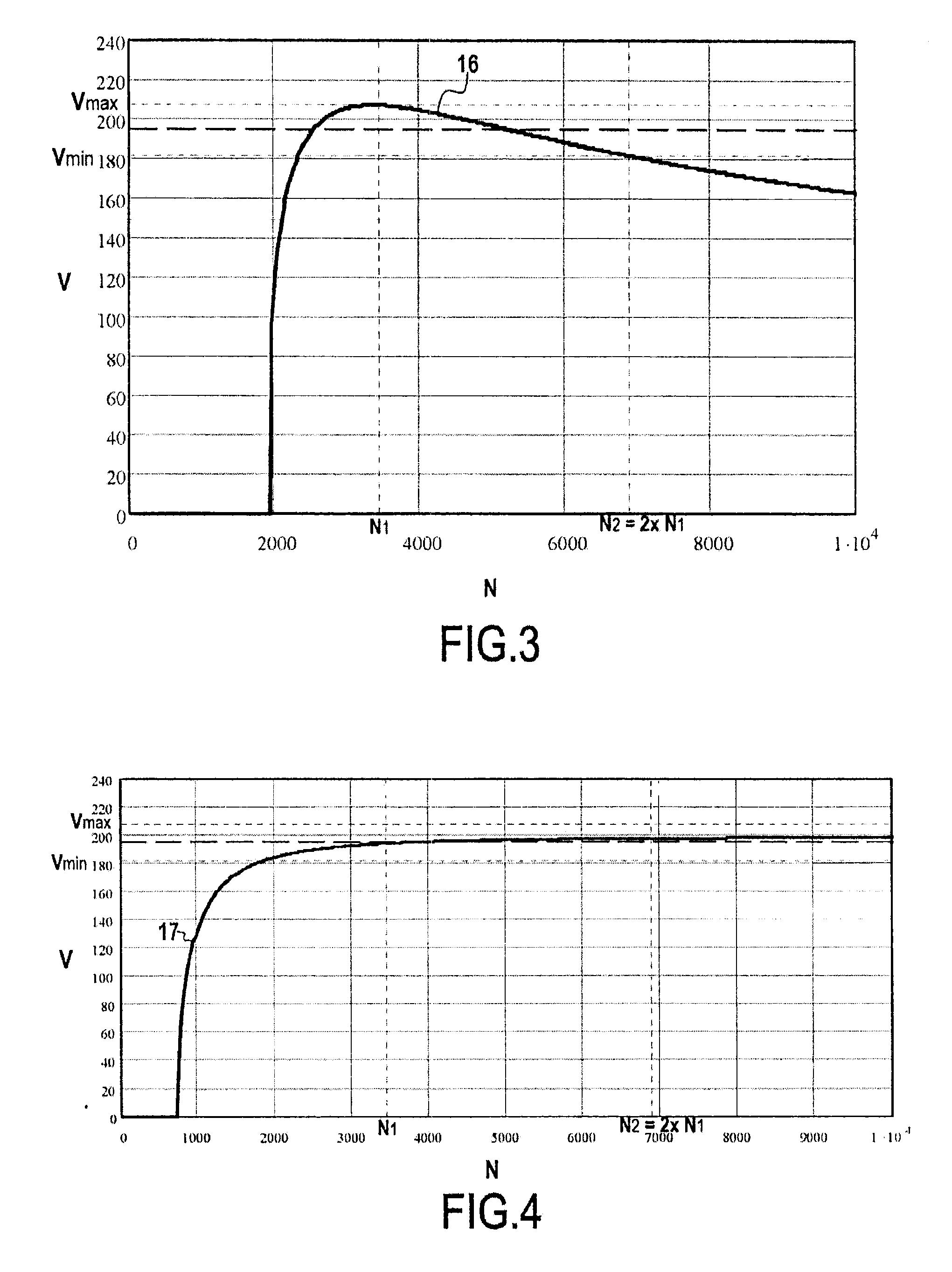
The invention allows for the use of an asynchronous machine to power electrical equipment in an aeroengine. The asynchronous machine is reliable, inexpensive, and can be easily incorporated in an aircraft. The excitation device needs to be designed only for the magnetization current of the asynchronous machine, which results in a simpler and more cost-effective device. The excitation device can also be designed with limited variation in amplitude, even if the speed of rotation of the engine changes. This ensures a constant voltage output for the electrical equipment. The invention also offers redundancy, improving the reliability of the power supply circuit, without adding size or cost.

Problems solved by technology

Nevertheless, the complexity of such a multistage synchronous generator generally involves a large amount of bulk, low reliability, and high cost.
It is also difficult to introduce redundancy when that is required for reliability reasons.

Method used


Image

  • Aircraft power supply circuit including an asynchronous machine
  • Aircraft power supply circuit including an asynchronous machine
  • Aircraft power supply circuit including an asynchronous machine

Examples


Embodiment Construction

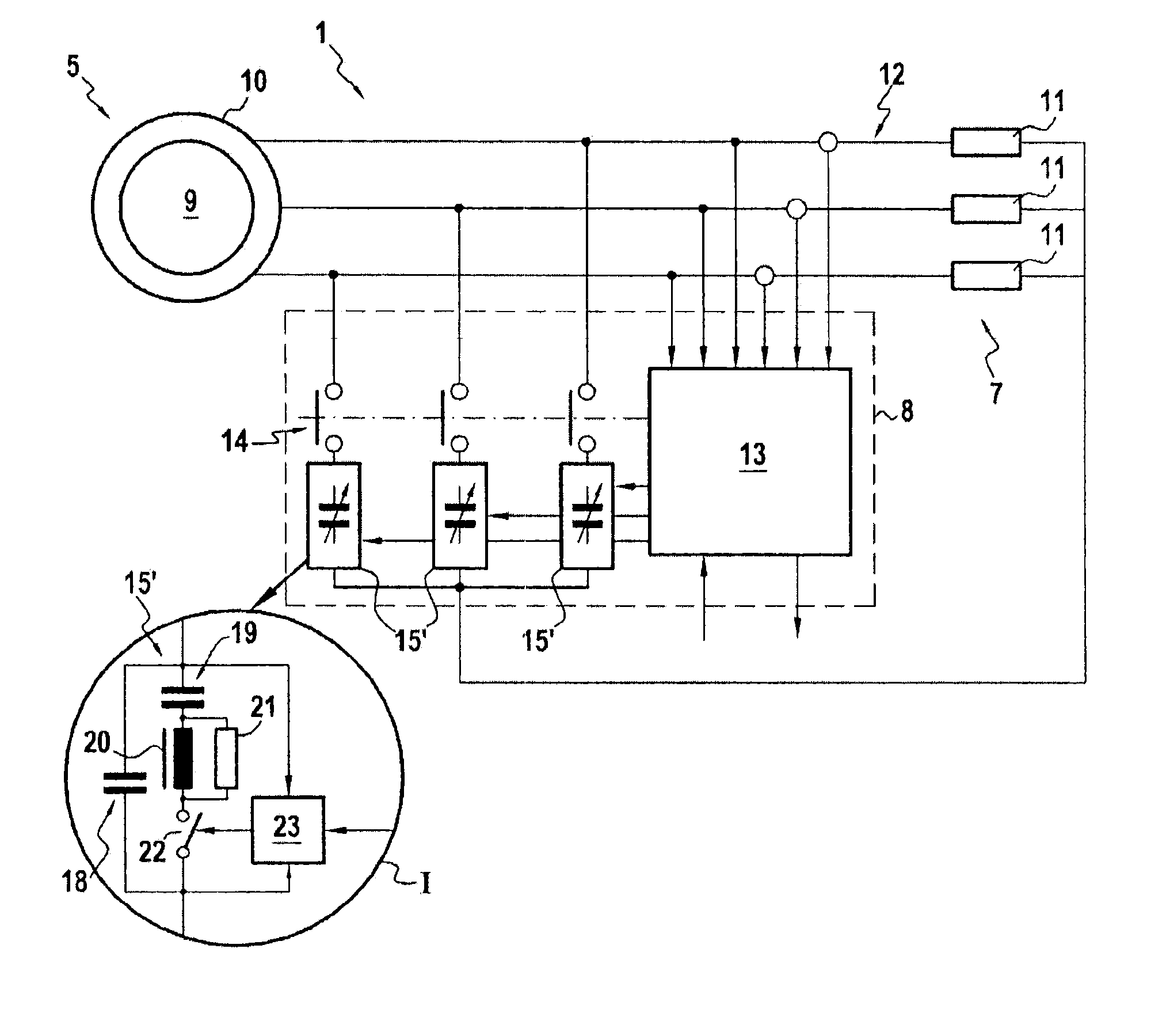
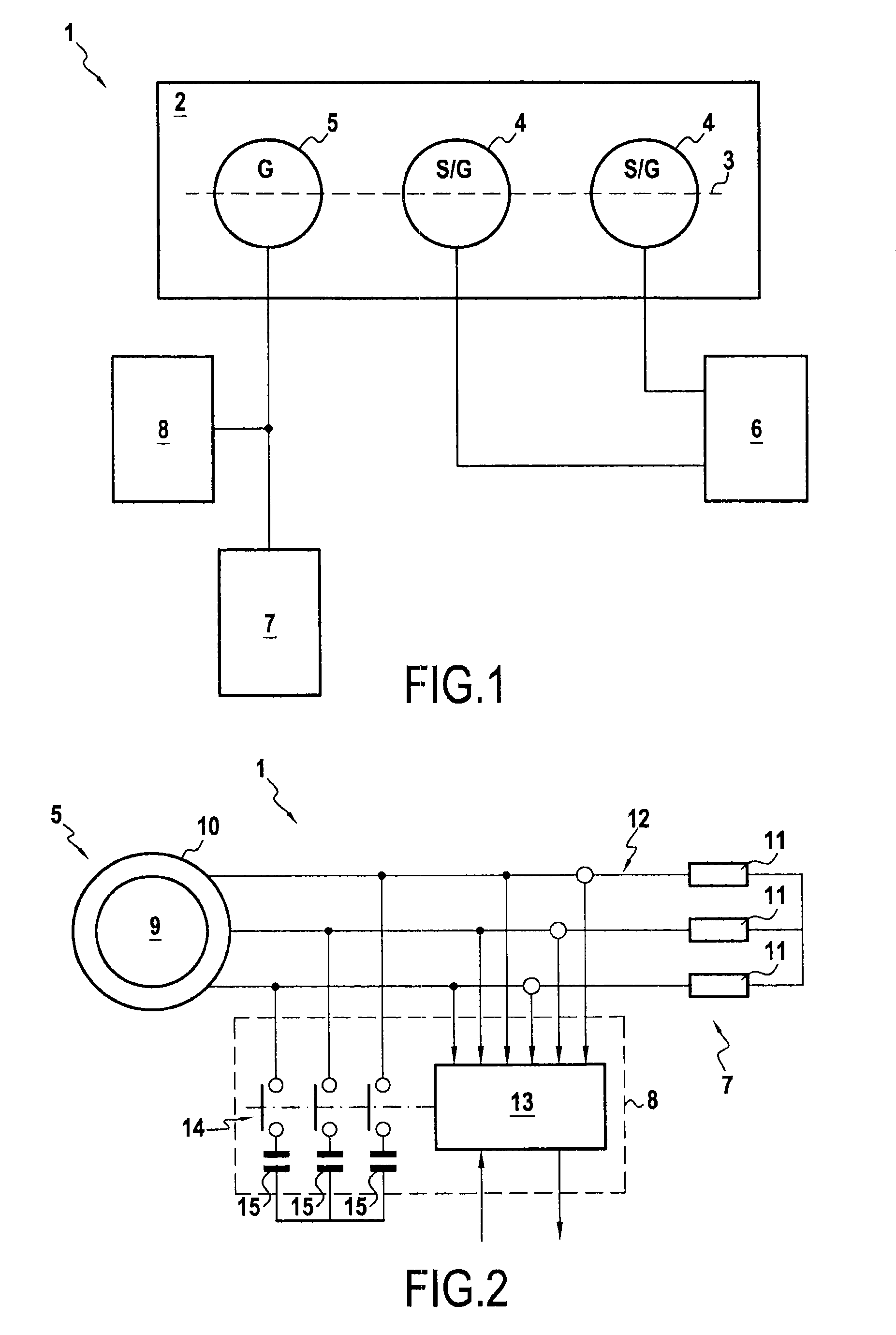
[0030]FIG. 1 shows a power supply circuit 1 in an embodiment of the invention, in its environment. The power supply circuit 1 is for powering a piece of electrical equipment 7 of an aircraft engine 2. By way of example, the engine 2 may be a gas turbine. The electrical equipment 7 is of the mainly-resistive type. For example, in the description below, it is considered that the electrical equipment 7 comprises a deicing circuit of the engine 2, made up of deicing resistors incorporated in the inlet edges of the engine 2.

[0031]The power supply circuit 1 comprises a power supply generator 5, the electrical equipment 7, and an exciter device 8. The power supply generator 5 may be driven in rotation by a shaft 3 of the engine 2. The shaft 3 is also connected to starter generators (S / G) 4 capable of operating as synchronous electric motors when starting the engine 2 and as synchronous generators when the engine 2 is in operation, e.g. for electrically powering the on-board network 6 of th...


PUM


Abstract

A power supply circuit for supplying electrical energy in an aircraft, the circuit including a power supply generator configured to be driven in rotation by the engine of the aircraft to power electrical equipment of the aircraft engine. The power supply generator includes an asynchronous machine connected to an excitation device. The asynchronous machine includes a rotor configured to be driven in rotation by the engine and a stator connected to the electrical equipment. The excitation device is configured to cause a reactive current of flow in the stator.

Description

BACKGROUND OF THE INVENTION[0001]The invention relates to electrically powering electrical equipment of an aeroengine.[0002]It is known to use an electricity generator incorporated in an engine of an aircraft in order to produce electrical energy for the purpose of powering electrical equipment associated with the engine. For example, document FR 2 911 848 describes a power supply generator connected to a deicing circuit of an aeroengine.[0003]The power supply generator used in that type of application is typically a synchronous generator having two or three stages. Such a synchronous generator enables an alternating voltage to be delivered that is well regulated and that has a good form factor. It is thus possible to deliver an alternating voltage of substantially constant amplitude, even when the speed of rotation of the engine driving the power supply generator varies. Nevertheless, the complexity of such a multistage synchronous generator generally involves a large amount of bul...

Claims


Application Information

Patent Timeline
Patent Type & Authority Patents(United States)
IPC IPC(8): H02P9/46
CPCH02P9/46H02P2009/005H02P2101/30
Inventor DE, WERGIFOSSE, ERIC
Owner SAFRAN ELECTRICAL & POWER
Learn More