Smoke detector with remote alarm silencing means

a smoke detector and remote alarm technology, applied in the direction of fire alarms, fire alarm smoke/gas actuation, instruments, etc., can solve the problems of inability to work anyway, requiring the user to repeat futile activity, hazardous, or even deadly conditions, etc., to achieve convenient repositioning, easy detection, and easy silence of the alarm of the smoke detector

Inactive Publication Date: 2014-09-30
MARKS MITCHELL J +1
View PDF12 Cites 47 Cited by
  • Summary
  • Abstract
  • Description
  • Claims
  • Application Information

AI Technical Summary

Benefits of technology

[0014]It is, therefore, a principal object of this invention to provide a new, useful, and uncomplicated smoke detector having a remote alarm silencing means in the form of a mountable remote control device but wherein the remote control device is not hand-held or hard-wired to the smoke detector and which emits electromagnetic waves of a given frequency to temporarily mute or silence the audio alarm of the smoke detector and which also allows remote testing of the detector. The remote control device is mountable yet easily relocatable as desired or required by the user. In this way, the silencing means remains in a given location or position where the user will be able to easily locate it and thus easily silence the alarm of the smoke detector. It is another object of the present invention that the remote control device of the present invention, or several of them, be used by the user to remotely silence the alarm of the smoke detector for a short pre-programmed period of time. The smoke detector could be alternatively configured to silence the alarm, reduce the volume of the alarm, and / or activate a visual indicator, such as a light, to indicate that the silencing means has been activated. It is still another object of the present invention to provide a smoke detector having a remote control device that is re-locatable with minimal effort throughout a variety of places within the home. It is still another object to provide a remote silencing device that can come as original equipment with a smoke detector or that can be separately purchased as a replacement unit, the electromagnetic frequency of the replacement unit matching that of the original remote silencing means. The remote control and the smoke detector would allow for “code learning” which allows for selective alarm actuation. It is yet another object of the present invention to provide a remote control device that has its own self-contained long-life battery for allowing the device to generate and transmit an electromagnetic wave, such as an RF signal, of sufficient energy to be detected by a receiver component within the smoke detector unit, the receiver component silencing the alarm of the smoke detector unit. It is still another object of the present invention to provide a remote control device that is to be used with the smoke detector of the present invention that is aesthetically-pleasing to the user and that may be purchased by the user in a personally-pleasing decorated fashion offered in a wide variety of shapes, colors, patterns and designs or that may be offered with interchangeable housings that come in a wide variety of shapes, colors, patterns and designs.
[0015]The present invention has obtained these objects. It provides for a smoke detector having a remote alarm silencing means wherein the remote means that is used is not hard-wired to the smoke detector and which allows the remote means to be mountable yet easily relocatable as desired or required. That is, the means, or several of them, can be used by the user to remotely silence the alarm of the smoke detector for a short pre-programmed period of time, the remote silencing means being generally re-locatable throughout a variety of places within the area and vicinity of the primary smoke detector unit. The remote alarm silencing means can also be configured to mute or silence the alarm, reduce its decibel level, and / or activate a visual indicator. The visual indicator could also be used as a means for remote testing of the operability of the smoke detector.
[0017]The present invention is drawn, in its preferred embodiment, to a smoke detector that employs an RF receiver in conjunction with a remote RF transmitter to silence the audible alarm in the event the detector was triggered by nuisance smoke. The smoke detector is mounted to the ceiling in similar fashion as standard smoke detectors. The remote RF transmitter, however, can be mounted in any convenient location within easy reach of the occupant or user. When the smoke detector sounds an audible alarm due to nuisance smoke, the user can quickly and conveniently press the button on the remote transmitter to silence the audible alarm of the smoke detector for a period of time.
[0018]Additionally, the RF transmitter of the present invention can be programmed with a unique “transmitter identification” or “ID” at the time of manufacture. This unique ID or identification would then be transmitted with each RF message to uniquely identify itself from other RF transmitters. At some time in the manufacturing process, the smoke detector and the remote RF transmitter can be paired in a fashion where the detector “learns” the unique ID of the transmitter and thereby will only silence the audible alarm if it receives an RF message from that particular transmitter. This is critical when several smoke detectors are installed in a building since a particular remote RF transmitter should only silence the audible alarm on the smoke detector it was intended to silence, not all of the detectors in the building or surrounding area. This unique ID also allows multiple RF transmitters to operate on the same RF frequency, thus greatly simplifying the manufacturing process.
[0019]To eliminate increased power consumption due to the RF receiver being required to “listen” for incoming RF messages, the present invention also implements means to activate the RF receiver only when the audible alarm has been activated. Once the audible alarm has been silenced or deactivated by the detector, the RF receiver would also be deactivated or put into a “sleep” mode. This approach absolutely minimizes energy consumption of the battery without compromising the “silence” feature of the present invention. As an example, if the RF receiver was allowed to operate continuously, it could very well receive an RF message from an RF transmitter with an ID that matched the ID stored within the detector. If this RF message was received when no audible alarm was active, the detector would not perform any function after receipt of the RF message (i.e., there is no alarm to silence). So there is no need to listen for RF messages unless the audible alarm is active anyway. In this regard, the smoke detector of the present invention allows the RF receiver to continuously “listen” for incoming RF messages only upon the occurrence of an alarm status within the smoke detector.

Problems solved by technology

One inconvenience that is often experienced in the use of such smoke detectors of current manufacture is the fact that the occupant of a home in which such detectors are used can create a “controlled” situation where “nuisance” smoke is emitted and the smoke detector becomes activated, thus sounding the audio alarm.
However, the nuisance smoke usually re-activates the smoke detector, thereby requiring the user to repeat this futile activity.
Unfortunately, this method requires that the battery be replaced at a later time anyway.
If forgotten, a hazardous, or even deadly, condition could exist.
And if the smoke detector is hard-wired into the circuitry of the home, this method won't work anyway.
Movement or relocation of appliances may work to make the switch impractical to use or even completely inaccessible.
The remote switch of this type, much like the proverbial television remote control, is not attachable to a vertical surface, such as a wall, and is prone to being lost or misplaced.
However, requiring a radio frequency (RF) receiver to continuously “listen” for incoming RF messages greatly increases power consumption and requires a much larger battery than is typically used in a smoke detector.
What is also needed is a primary detector unit that includes a battery-access port having a screw within it for preventing the easy removal of the battery from the smoke detector, or at least making it less convenient to remove the battery than in a unit where the battery-access port does not include the screw.

Method used


Image

  • Smoke detector with remote alarm silencing means
  • Smoke detector with remote alarm silencing means
  • Smoke detector with remote alarm silencing means

Examples


Embodiment Construction

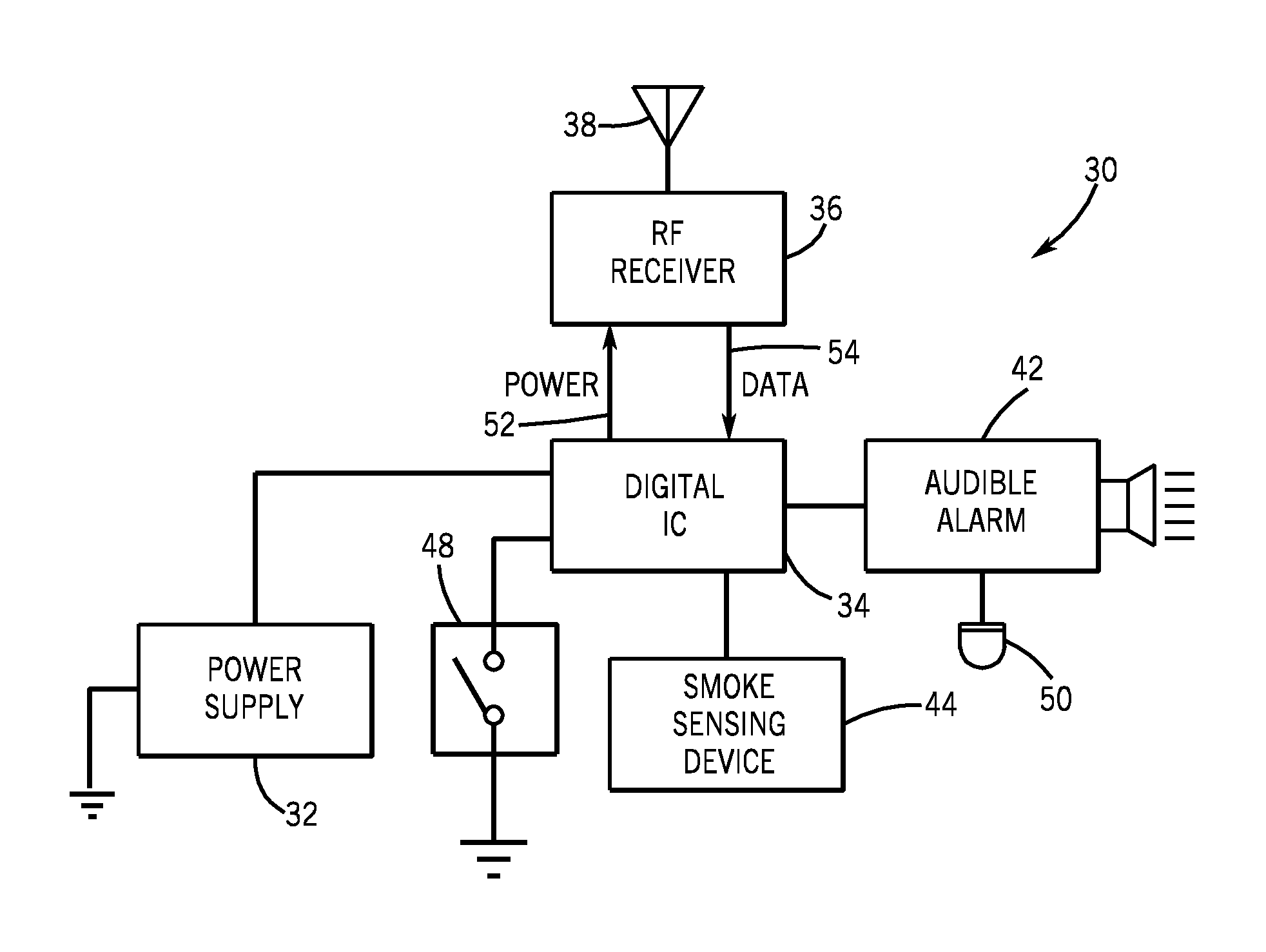
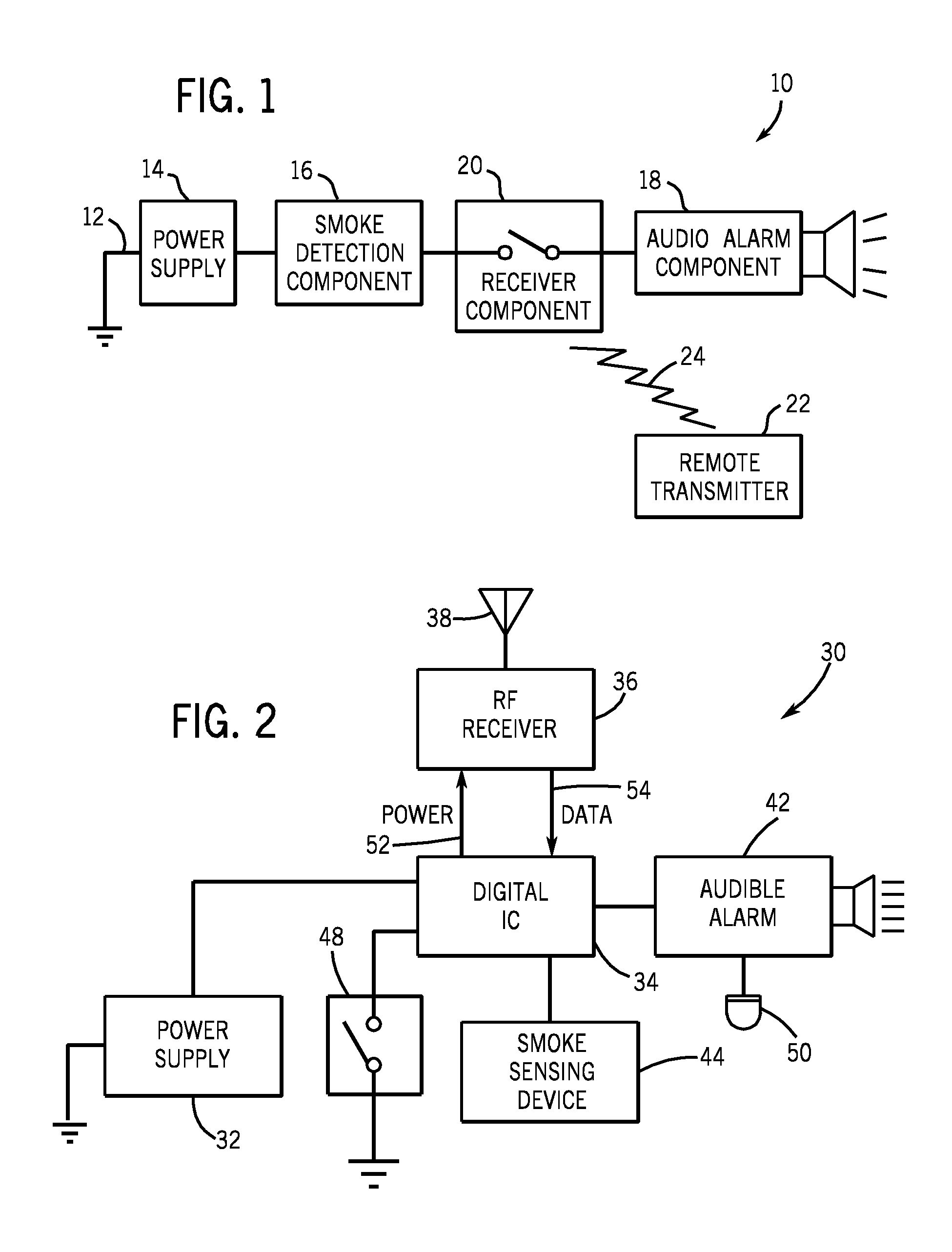
[0028]Referring now to the drawings in detail, wherein like numbered elements refer to like elements throughout, FIG. 1 illustrates a simplified schematic diagram of a first preferred embodiment of the circuit, generally identified 10, that is used in the smoke detector of the present invention. The circuit 10 includes a power supply 14, a smoke detection component 16, an audio alarm component 18, and a receiver component 20. These components are electrically connected 12. The circuit 10 also includes a component that is not electrically connected to the other components in the usual sense. More specifically, the circuit 10 includes a remote wireless transmitter 22 that emits and transmits electromagnetic waves 24 to actuate the receiver component 20 of the circuit 10. The remote transmitter 22 operates on conventional direct current batteries of the type that are compact and commercially available today. The precise voltage is not a limitation of the present invention. The preferre...


PUM


Abstract

A smoke detector employs a receiver and a remote transmitter to silence the audible alarm of the smoke detector in the event the detector was triggered by nuisance smoke. The receiver and transmitter circuits are designed to operate in a no-power or low-power consumption mode until the alarm is activated or the remote transmitter is actuated.

Description

[0001]This application claims the benefit and priority of U.S. Provisional Pat. App. No. 60 / 726,051 filed Oct. 12, 2005.FIELD OF THE INVENTION[0002]This invention relates generally to devices that are used in homes for the detection of smoke, such devices emitting an audio alarm signal of some sort to alert the occupants of a home that smoke, and perhaps a fire that is the source of the smoke, has been detected by the device. More particularly, this invention relates to a smoke detector that includes a wireless remote alarm silencing means such that the user, knowing that the source of the smoke is harmless or is under control, may remotely silence the alarm of the smoke detector for a pre-programmed or a pre-programmable period of time. It also relates to such a smoke detector where the silencing means is removably locatable with minimal effort by the user and is preferably an easily replaceable item.BACKGROUND OF THE INVENTION[0003]Smoke detectors are well known in the art. Smoke ...

Claims


Application Information

Patent Timeline
Patent Type & Authority Patents(United States)
IPC IPC(8): G08B17/10G08B29/14
CPCG08B29/145G08B17/10
Inventor MARKS, MITCHELL J.RICHEY, JAMES N.
Owner MARKS MITCHELL J
Why Eureka
Try Eureka