Electronic device with invisible light touch panel

a technology of touch panel and electronic device, which is applied in the direction of instruments, measurement apparatus components, computing, etc., can solve the problems of increasing circuit disposition and mechanical disposition difficulty of the volume of the light guide plate of the conventional infrared touch panel, so as to reduce the manufacturing cost of the product, reduce the modeling cost, and increase the diversity of the industry

Active Publication Date: 2014-09-30
WISTRON CORP
View PDF13 Cites 5 Cited by
  • Summary
  • Abstract
  • Description
  • Claims
  • Application Information

AI Technical Summary

Benefits of technology

[0020]The present invention utilizes the inactive area on the light guiding plate to be the indication button and the decoration bar, so as to decrease modeling cost and to increase diversity of the industry design. Therefore, the light guiding plate of the present invention can decrease manufacturing cost of the product, and economize the inner space of the electronic device for providing other use of circuit design and mechanism design.

Problems solved by technology

Therefore, the light guide plate of the conventional infrared touch panel has huge volume.
Difficulty of circuit disposition and mechanical disposition of the conventional infrared touch panel is increased due to the mechanical design constraint of the indication lights.

Method used


Image

  • Electronic device with invisible light touch panel
  • Electronic device with invisible light touch panel
  • Electronic device with invisible light touch panel

Examples


Embodiment Construction

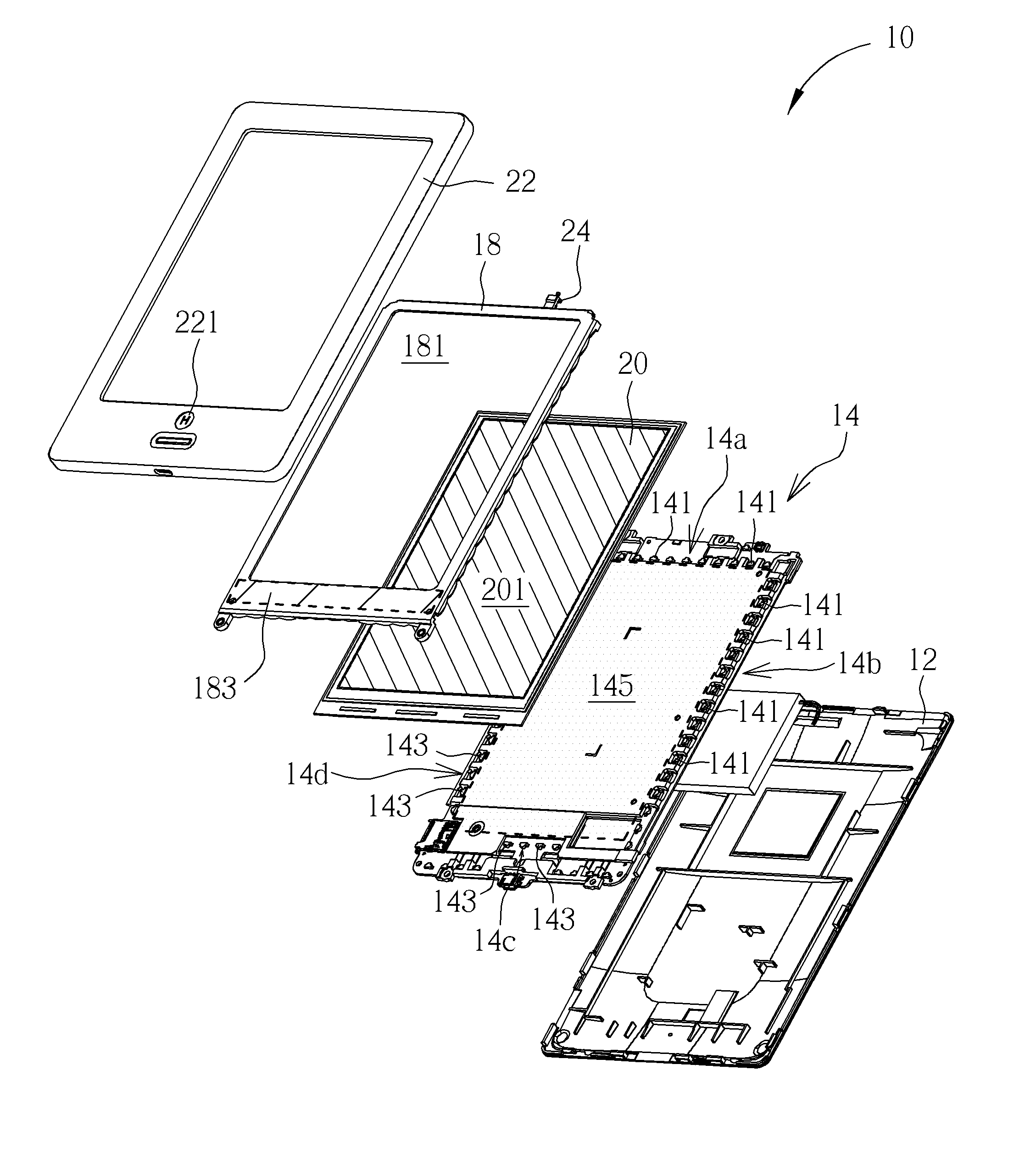
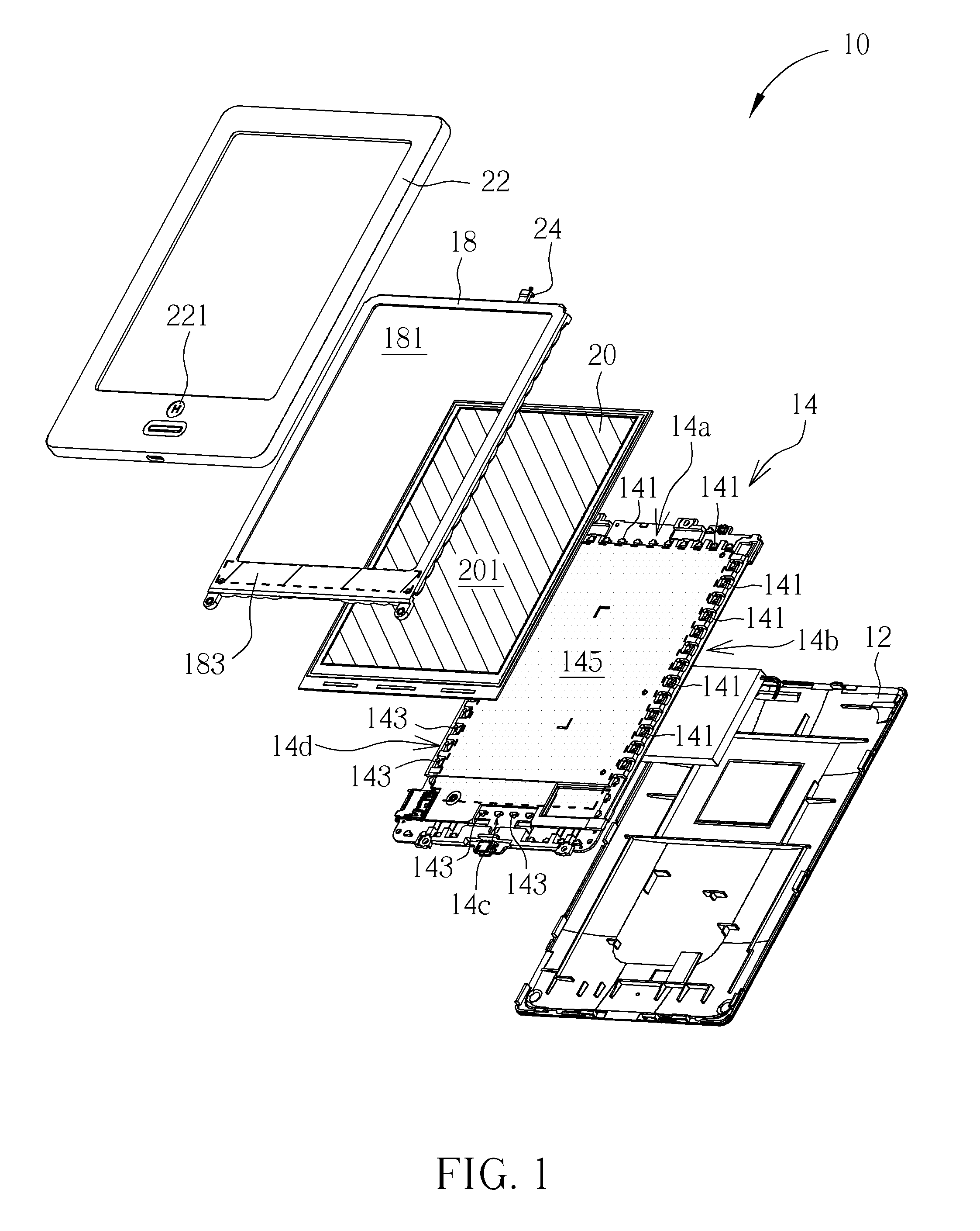
[0026]Please refer to FIG. 1 to FIG. 4. FIG. 1 and FIG. 2 respectively are exploded diagrams of an electronic device 10 in different views according to an embodiment of the present invention. FIG. 3 is an assembly diagram of the electronic device 10 according to the embodiment of the present invention. FIG. 4 is a sectional view of the electronic device 10 along Line A-A′ according to the embodiment of the present invention. The electronic device 10 of the present invention can be a tablet computer with an invisible light touch panel. The invisible light touch panel can be an infrared touch panel, and the infrared touch panel utilizes a plurality of infrared emitters and a plurality of infrared receivers to form an infrared network above a surface of the touch panel. When an object moves into the infrared network to contact the touch panel, an infrared signal emitted from the infrared emitter is interfered, the corresponding infrared receiver receives the interfered infrared signal,...


PUM


Abstract

An electronic device with an invisible light touch panel is disclosed in the present invention. The electronic device includes a circuit board, a visible light source, a light guiding plate, a panel and a cover. The circuit board includes a plurality of invisible light emitters and receivers. The light guiding plate includes an active area and an inactive area. The invisible light outputted from the invisible light emitter transmits to the invisible light receiver via the active area, and the visible light outputted from the visible light source can transmit to the inactive area. The cover is disposed above the light guiding plate. A hole is formed on a surface of the cover, and a position of the hole corresponds to the inactive area on the light guiding plate, so the visible light outputted from the visible light source passes through the cover via the inactive area and the hole.

Description

BACKGROUND OF THE INVENTION[0001]1. Field of the Invention[0002]The present invention relates to an electronic device with a touch panel, and more particularly, to an electronic device with an invisible light touch panel, and a light guiding plate of the electronic device can be an indicating button or a light bar for decoration.[0003]2. Description of the Prior Art[0004]A conventional infrared touch panel disposes a plurality of infrared receivers and a plurality of infrared emitters respectively on four sides of a circuit board. The infrared emitters disposed around the circuit board simultaneously generate infrared signals to the opposite infrared receivers, so an infrared network can be formed above a surface of the circuit board. When a user purposes to control the touch panel, the user can utilize an object to slide over the touch panel. The object can be a finger or a stylus. A part of infrared signal is interdicted when the object moves into the infrared network. Because eac...

Claims


Application Information

Patent Timeline
Patent Type & Authority Patents(United States)
IPC IPC(8): G06F3/042
CPCG06F3/0421G06F2203/04103
Inventor HUANG, SHENG-SHANKAO, SHIH-WANG
Owner WISTRON CORP
Why Eureka
Try Eureka