Security element and method for producing a security element

a technology of security elements and elements, applied in the field of security elements, can solve the problems of difficult subsequent separation of layers, inability to imitate impressions by optical copying methods,

Inactive Publication Date: 2014-09-30
LEONHARD KURZ STIFTUNG & CO KG
View PDF16 Cites 4 Cited by
  • Summary
  • Abstract
  • Description
  • Claims
  • Application Information

AI Technical Summary

Benefits of technology

[0009]The invention provides a security element which can be counterfeited only with great difficulty and can nevertheless be manufactured in an expedient manner. By virtue of the arrangement of the partial metallic layer between the volume hologram layer and the replication layer, in which the relief structure is molded, on the one hand the optical effect of the domains of the volume hologram layer which lie below the metallic layer in the first zones is suppressed, and on the other hand the optical effect of the relief structure is caused to be manifested in these zones. A seamless transition of the different optical effects generated in the first and second zones is thus brought about, without the volume hologram layer and the relief structure having to be partially applied in a registered fashion with respect to one another. As a result, the first and second information items are generated in an undistorted manner and with high luminous intensity in domains lying alongside one another with register accuracy, as a result of which a brilliant and impressive optically variable overall impression arises for the observer. Moreover, this impression cannot be imitated by an optical copying method since the optically variable effect produced by the volume hologram layer, on the one hand, and the optically variable effect produced by the replication layer with the metallic layer situated beneath it, on the other hand, in each case cannot be imitated by means of the respective other technology, and the structures generating the first and the second optically variable information items thus mutually protect one another against counterfeiting. Furthermore, an intimate connection of the structures providing the first and second information items is obtained by means of the sequence of the layers, such that the attempt to manipulate one structure automatically influences the optical impression of the other structure, such that any attempt at manipulation is immediately recognizable. Moreover, in the method according to the invention an intimate connection of the layers is obtained by virtue of the fact that the volume hologram is written in the volume hologram layer through the partial metallic layer and the partial metallic layer thus furthermore also produces the function of an exposure mask for writing the volume hologram. Thus, firstly, subsequent separation of the layers is made more difficult and, secondly, such an attempt at manipulation is immediately recognizable since the volume hologram layer has domains in which no volume hologram is written into the layer.
[0049]Preferably, the first regions for this purpose have a smallest dimension of less than 400 μm preferably of less than 200 μm. This has the effect that the splitting into first and second regions can no longer be resolved by the human observer and a continuous image impression thus arises. The smallest dimensions of the first regions preferably have a smallest dimension of more than 20 μm in order to ensure reliable filling of the first regions with the volume hologram material.

Problems solved by technology

Moreover, this impression cannot be imitated by an optical copying method since the optically variable effect produced by the volume hologram layer, on the one hand, and the optically variable effect produced by the replication layer with the metallic layer situated beneath it, on the other hand, in each case cannot be imitated by means of the respective other technology, and the structures generating the first and the second optically variable information items thus mutually protect one another against counterfeiting.
Thus, firstly, subsequent separation of the layers is made more difficult and, secondly, such an attempt at manipulation is immediately recognizable since the volume hologram layer has domains in which no volume hologram is written into the layer.

Method used


Image

  • Security element and method for producing a security element
  • Security element and method for producing a security element
  • Security element and method for producing a security element

Examples


Embodiment Construction

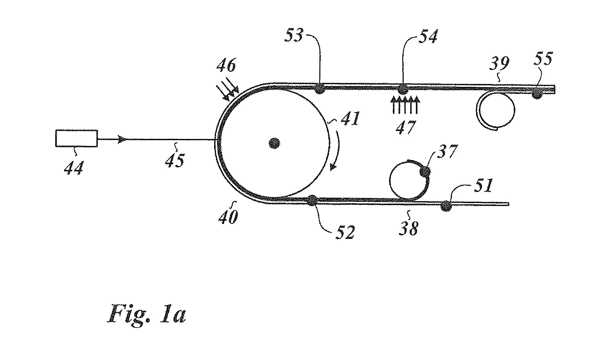
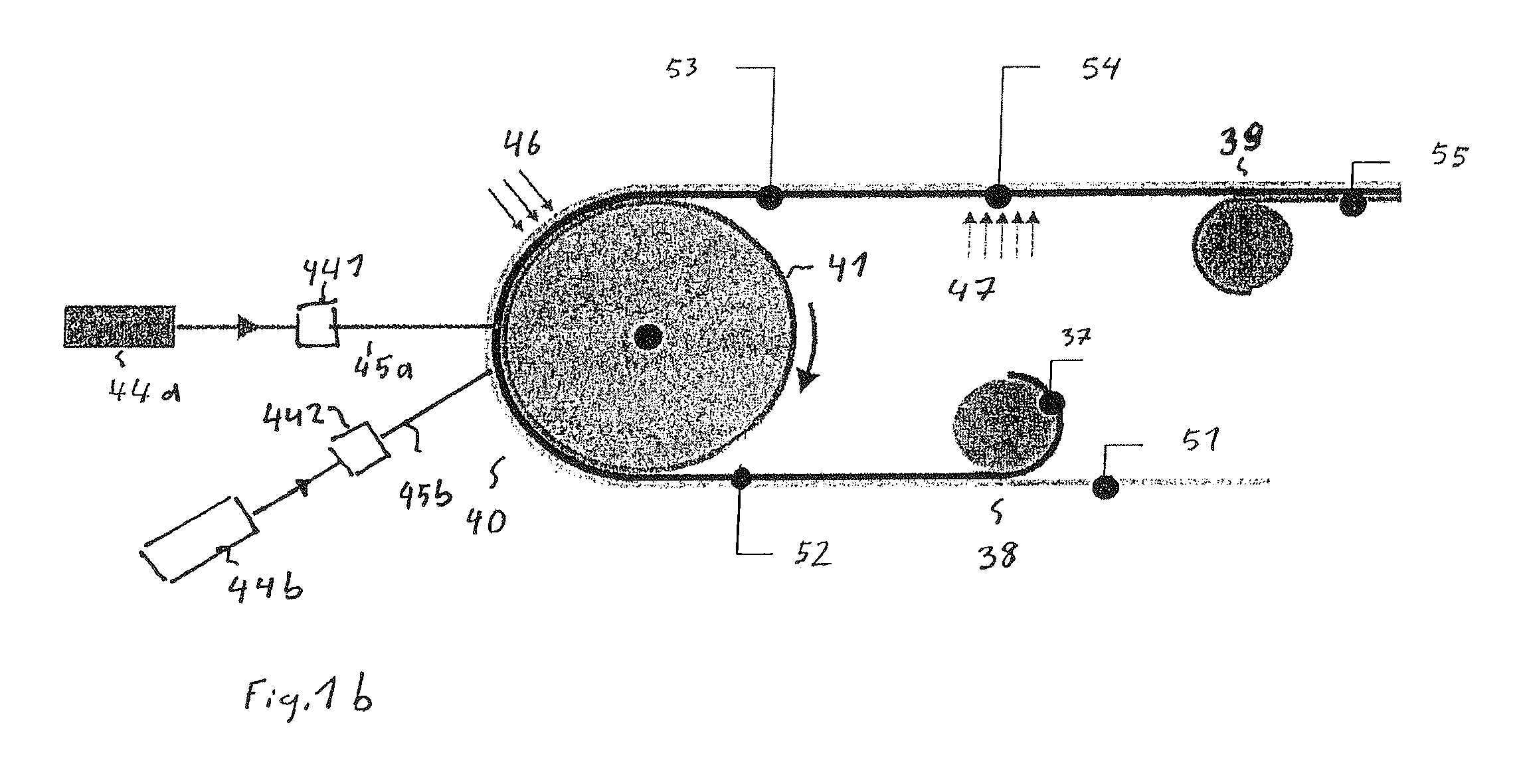
[0068]FIG. 1a illustrates the procedure when producing a security element according to the invention. FIG. 1a shows a coating station 38, an exposure station 40, an exposure station 47 and a coating station 39. A film body 51 is fed to the coating station 38. A volume hologram layer is applied on the film body 51 by the coating station 38, for example by a surface of the film body 51 being coated over the whole area or partially with a photopolymer material 37, which forms the volume hologram layer, by printing, spraying or pouring. The resultant multilayer body 52 is subsequently fed to the exposure station 40, where, for the purpose of recording a volume hologram into the volume hologram layer, it is exposed with coherent light 45 from the laser 44 and subsequently irradiated by the UV light source 46. The resultant multilayer body 53 is fed to the exposure station 47 in order to achieve complete curing of the volume hologram layer. The resultant multilayer body 54 is fed to the c...


PUM


Abstract

A method for producing a security element (55) and a security element (55) in the form of a multilayered film body having a top side facing the observer. The security element (55) has a volume hologram layer, in which a volume hologram is recorded, which provides a first optically variable information item. The security element (55) has a replication layer, in the surface of which a relief structure providing a second optically variable information item is molded and which is arranged above the volume hologram layer. A partial metallic layer is arranged between the volume hologram layer and the replication layer, wherein the metallic layer is provided in one or a plurality of first zones of the security element and the metallic layer is not provided in one or a plurality of second zones of the security element.

Description

[0001]This application is a divisional application of U.S. application Ser. No. 12 / 936,225, filed Nov. 1, 2010, which claims priority based on an International Application filed under the Patent Cooperation Treaty, PCT / EP2009 / 002419, filed on Apr. 2, 2009 and German Application No. DE 102008017652.4-45, filed on Apr. 4, 2008.BACKGROUND OF THE INVENTION[0002]The invention relates to a security element in the form of a multilayered film body having a volume hologram layer, and to a method for producing such a security element.[0003]Holograms are used as security elements for protecting security documents such as banknotes, money substitutes, credit cards, passports or ID documents and also for product protection. In mass-produced products, surface holograms are often used, by means of which interesting optically variable effects, for example movement effects, can be obtained and which are distinguished by a high luminous intensity.[0004]Volume holograms, also referred to as white ligh...

Claims


Application Information

Patent Timeline
Patent Type & Authority Patents(United States)
IPC IPC(8): G03H1/18G03H1/20G03H1/28B42D25/00G03H1/26G03H1/00G03H1/04G03H1/02
CPCG03H2210/54G03H2001/188G03H1/0011G03H1/041G03H1/18G03H1/0236G03H2001/0415G03H2270/54B42D15/10G03H2250/36B42D15/105B42D25/328G03H1/28G03H2001/2635B42D25/00G03H1/0244G03H2001/207G03H1/0248G03H2001/187B42D25/41B42D25/435
Inventor TOMPKIN, WAYNE ROBERTLUTZ, NORBERTBURKHARDT, MARKUSSCHARFENBERG, MICHAEL
Owner LEONHARD KURZ STIFTUNG & CO KG
Why Eureka
Try Eureka