Valve timing control apparatus
a timing control and valve technology, applied in the direction of process and machine control, brake systems, instruments, etc., can solve the problem of late introduction of working fluid into the chamber, and achieve the effect of less engine operation state changes and rapid changes
- Summary
- Abstract
- Description
- Claims
- Application Information
AI Technical Summary
Benefits of technology
Problems solved by technology
Method used
Image
Examples
first embodiment
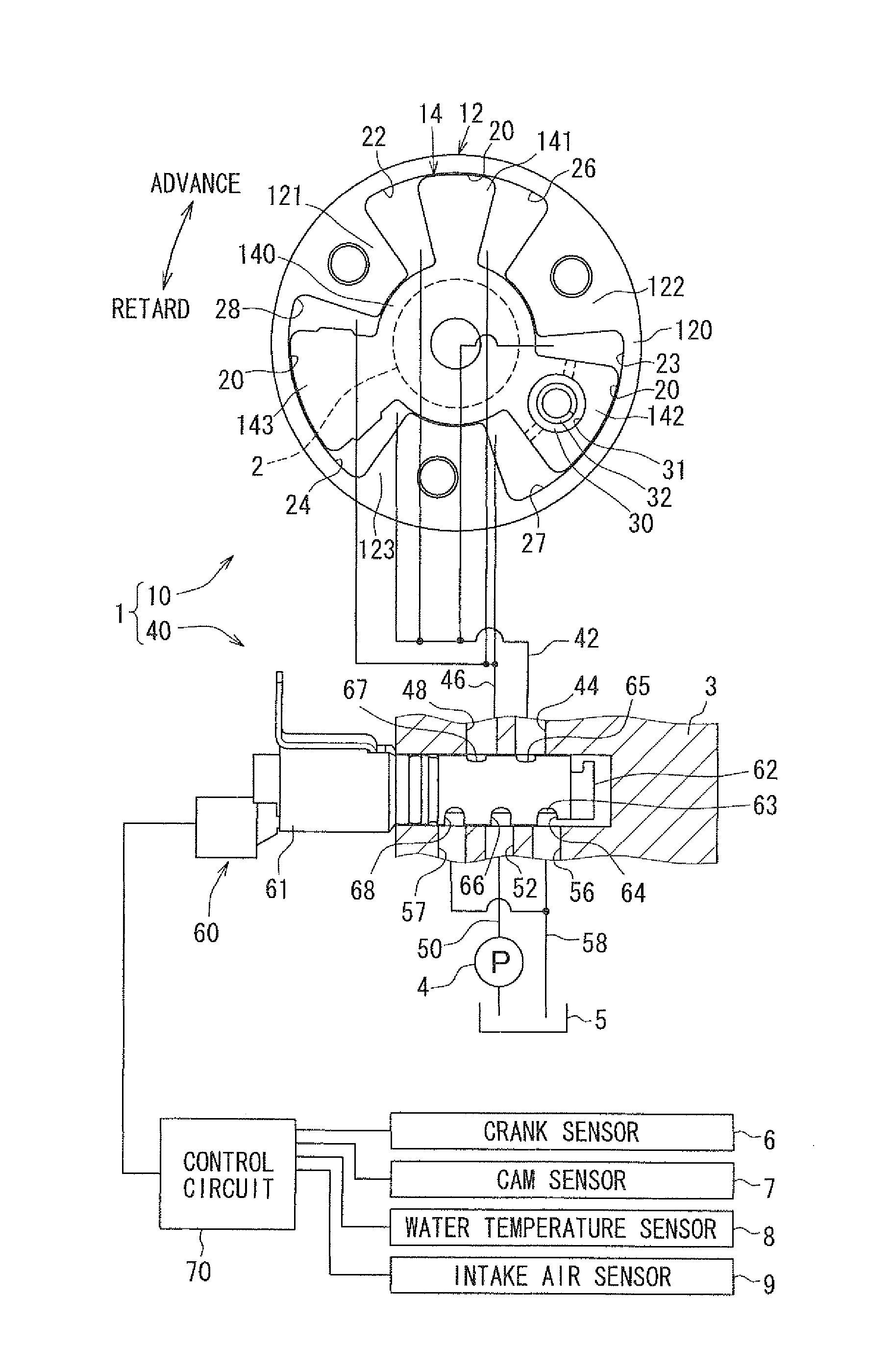
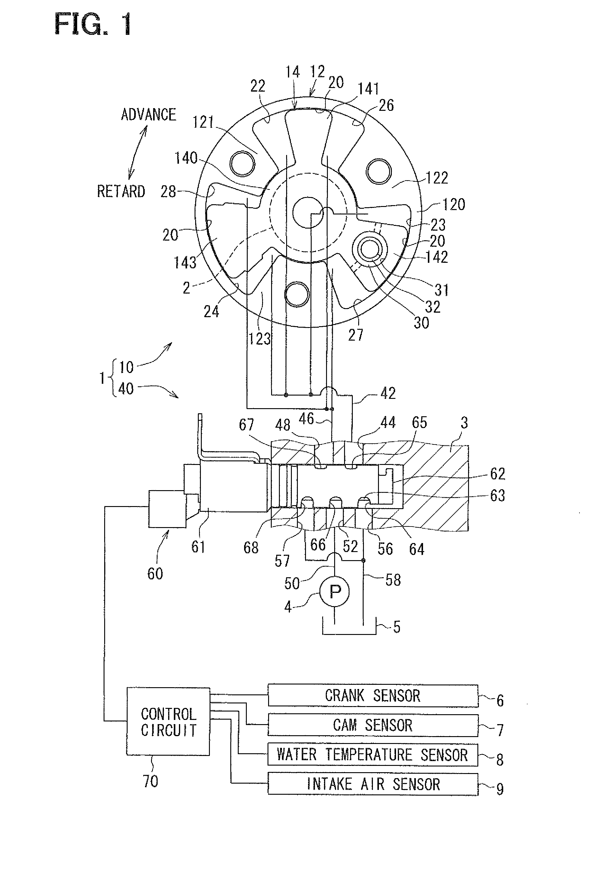
[0037]A valve timing control apparatus 1 according to a first embodiment of the present invention is applied to an internal combustion engine of a vehicle, for example. The valve timing control apparatus 1 controls valve timing of an intake valve serving as a “valve” that is opened or closed by a camshaft 2 using working oil serving as “working fluid”. As shown in FIG. 1, the valve timing control apparatus 1 has a driving unit 10 and a controller 40. The driving unit 10 is provided in a driving force transmission system to transmit a driving force of a crankshaft (not shown) of the internal combustion engine to the camshaft 2, and is driven with working oil. The controller 40 controls supply of working oil to the driving unit 10.
(Driving Unit)
[0038]The driving unit 10 has a housing 12 made of metal. The housing 12 has a cylindrical portion 120, and multiple shoes 121, 122, 123 serving as partition members. The respective shoes 121, 122, 123 are arranged in the cylindrical portion 12...
second embodiment
[0075]As shown in FIG. 4, S200 is added after S103 in a second embodiment, compared with the first embodiment.
[0076]Specifically, at S200, it is determined whether the engine has a fuel-cut state in which fuel injection is cut in a cylinder of the engine. If the engine has the fuel-cut state in S200, the compulsory mode is set in S104, so that the rotation phase is alternately changed. If the engine does not have the fuel-cut state in S200, the control flow returns to S101 by skipping S104 and S105.
[0077]According to the second embodiment, when the fuel injection is cut in the cylinder of the engine, fuel combustion in the cylinder is stopped, so that a rapid change in the engine operation state becomes difficult to be generated by the compulsory change of the rotation phase. Therefore, the rotation phase is compulsorily changed not only when the engine shifts to the high rotation state but also when the fuel injection is cut in the cylinder of the engine. Thus, the change in the en...
third embodiment
[0079]As shown in FIGS. 5, S300, S301 and S302 are added after S104 in a third embodiment, compared with the first embodiment.
[0080]Specifically, it is determined whether an abnormality is generated at S300. If the rotation phase does not reach one of the most advance phase and the most retard phase when the rotation phase is compulsorily changed, it is determined that the abnormality is generated. If the abnormality is not generated, the control flow proceeds to S105. If the abnormality is generated, the control flow proceeds to S301.
[0081]At S301, the engine control status is set as a fail-safe mode as for a flow of working oil with respect to the chamber 22, 23, 24, 26, 27, 28. In the fail-safe mode switched from the compulsory mode, the rotation phase is compulsorily locked into a phase opposite from the most advance phase or the most retard phase to which the rotation phase does not reach, by controlling the energization of the solenoid 61.
[0082]That is, if the rotation phase d...
PUM
 Abstract
Description
Claims
Application Information
 - R&D
- Intellectual Property
- Life Sciences
- Materials
- Tech Scout
- Unparalleled Data Quality
- Higher Quality Content
- 60% Fewer Hallucinations
Browse by: Latest US Patents, China's latest patents, Technical Efficacy Thesaurus, Application Domain, Technology Topic, Popular Technical Reports.
© 2025 PatSnap. All rights reserved.Legal|Privacy policy|Modern Slavery Act Transparency Statement|Sitemap|About US| Contact US: help@patsnap.com


