An ultrasonic probe rotating device and its use method and application

A technology of ultrasonic probe and rotating device, which is applied in the field of medical equipment for prostate surgery. It can solve problems such as damage to the protective cover of the ultrasonic probe, increase in the complexity of the mechanical structure, and deformation of the target scanning organ, so as to simplify the mechanical complexity and facilitate the handling of emergencies. situation, the effect of enhancing safety

Active Publication Date: 2017-11-28
BEST MEDICAL ROBOT TECHNOLOGY (TIANJIN) CO LTD
View PDF6 Cites 0 Cited by
  • Summary
  • Abstract
  • Description
  • Claims
  • Application Information

AI Technical Summary

Problems solved by technology

[0006] 2. In the prior art, in order to realize the transmission structure of the rotation of the ultrasonic probe, the gear connection mode is mostly used, and the output shaft of the motor is driven to drive the rotation of the ultrasonic probe. Additional structures and spaces are required for fixing the gears, which occupy a large operating space. Increased mechanical complexity
At the same time, there is a certain error in the gear transmission, which affects the accuracy of the equipment
[0007] 3. Among the intracavity ultrasonic probes currently used, there are many asymmetrical ultrasonic probes (that is, the central axis of the front of the probe does not coincide with the central axis of the handle, for example, the front end of the probe is thin and the end of the handle is thick); The probe device mostly adopts a symmetrical structure and a uniform thickness design, and it rotates around the central axis of the clamped part (ultrasound probe handle) by default, rather than around the central axis of the target rotating part (front part of the ultrasonic probe) in the cavity. Directly cause the ultrasonic probe to rotate eccentrically in the human body, which may cause the deformation of the target scanning organ, reduce the imaging accuracy, and even damage the protective cover of the ultrasonic probe, causing harm to the patient and causing medical accidents

Method used


Image

  • An ultrasonic probe rotating device and its use method and application
  • An ultrasonic probe rotating device and its use method and application
  • An ultrasonic probe rotating device and its use method and application

Examples


Embodiment Construction

[0028] The technical solutions of the present invention will be further described below in conjunction with specific embodiments.

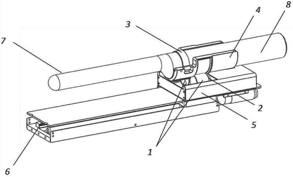
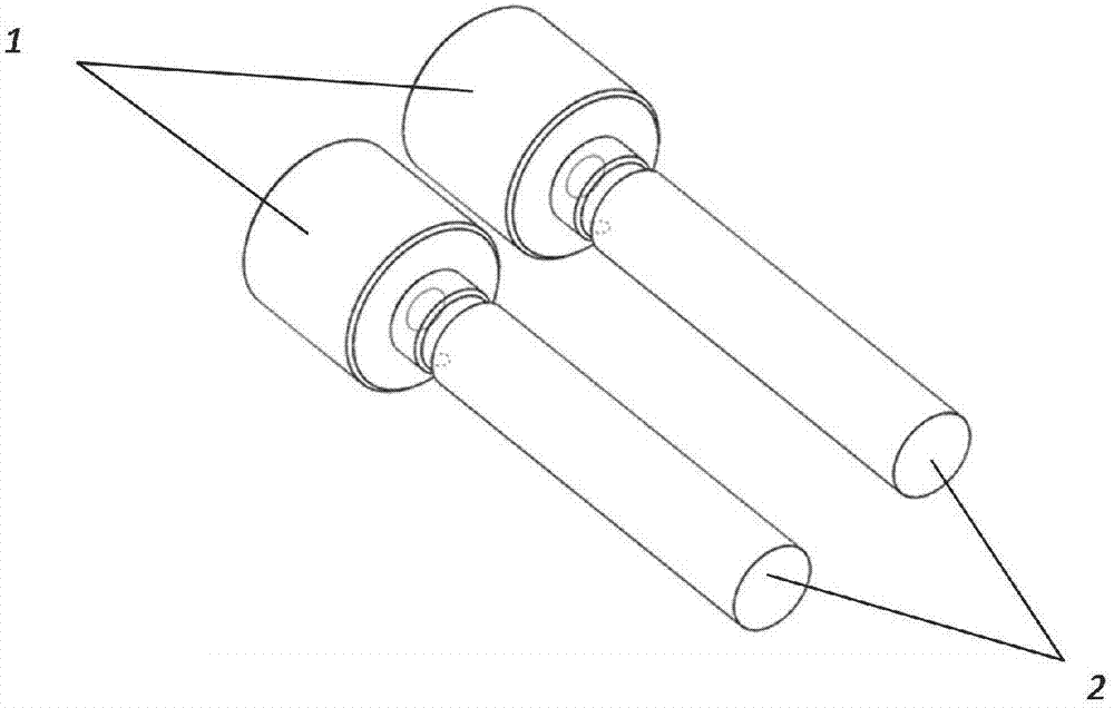
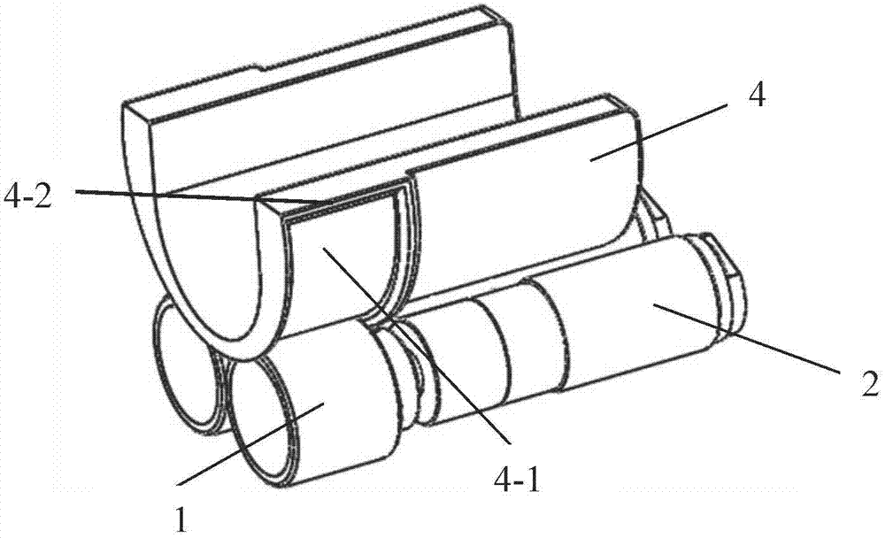
[0029] as attached figure 1 As shown, an asymmetrical ultrasonic probe is used, that is, the central axis of the front part of the probe does not coincide with the central axis of the handle, the front end of the probe is thin, and the handle end is thick. be fixed. The (rotating) magnet is connected to the output shaft of the (rotating) motor, and the magnet and the motor are fixedly installed in the fixture. The joint between the rotating guide part and the rotating magnet, that is, the outer circumference of the rotating guide part and the outer circumference of the rotating magnet are in phase. Cutting, the rotating guide part and the rotating magnet are adsorbed together by magnetic force. At this time, the rotating motor drives the rotating magnet connected to it to rotate. The rotation of the magnet is magnetically attracted to drive the e...


PUM


Abstract

The invention discloses an ultrasonic probe rotating device and its use method and application. It mainly includes a rotating magnet, a rotating motor and a rotating guide component. The rotating magnet is connected to the output shaft of the rotating motor. The side surface of the rotating magnet is tangent to the outer circumference of the rotating guide member. The technical scheme of the present invention drives the rotating motor to drive the magnet to rotate the rotating guiding part and control it in time at the same time. At the same time, the rotating guiding part compensates the undesired displacement of the asymmetric structure ultrasonic probe, avoiding the loss of control of the motor or the undesired displacement causing the target organ deformation, equipment damage, and even accidental injury to the recipient, improving system security.

Description

technical field [0001] The invention relates to the field of medical equipment, more specifically, to a medical equipment for prostate surgery. Background technique [0002] The prostate is a very rare gonadal gland with both internal and external secretion functions, such as a chestnut, with the bottom facing up and attached to the bladder, the tip facing down, touching the urogenital diaphragm, the pubic symphysis on the front, and the rectum on the back. The urethra passes through the middle of the prostate gland and guards the upper opening of the urethra. Therefore, if the prostate is diseased, urination will be affected first. When there are lesions in the prostate, one method is "digital rectal examination", which involves feeling the back of the prostate and making judgments based on the doctor's experience. The other method is to perform a prostate biopsy, that is, to take a small part of the prostate tissue as a sample. Pathologists or professional doctors examine...

Claims


Application Information

Patent Timeline
Patent Type & Authority Patents(China)
IPC IPC(8): A61B8/12
Inventor 张旭许勇俞鸿凯时一宝边东东孟宪全张茜
Owner BEST MEDICAL ROBOT TECHNOLOGY (TIANJIN) CO LTD
Why Eureka
Try Eureka