Manually-operated boat canopy system

a man-operated, boat technology, applied in waterborne vessels, special-purpose vessels, vessel construction, etc., can solve the problems of manual systems, affecting the operation of boats, and affecting the operation of boats, and achieves the effect of simple operation and easy retrofitting

Active Publication Date: 2014-10-14
LIPPERT COMPONENTS MFG INC
View PDF6 Cites 27 Cited by
  • Summary
  • Abstract
  • Description
  • Claims
  • Application Information

AI Technical Summary

Benefits of technology

[0006]Accordingly, it is a general purpose and object of the present invention to provide an improved canopy deployment system for boats that is simple to operate and easily retrofitted to existing boat structure for providing extended sunshade protection to those on board the boat without causing obstructions upon the deck.
[0007]A more particular object of the present invention is to provide an improved canopy deployment system for recreational boats that is lightweight and self-supporting in its assembled structure and readily mountable to existing rooftop structure on the boat to provide extended sunshade protection whenever needed and without presenting obstructions to the movement or performance of those on or around the deck.
[0008]Another object of the present invention is to provide an improved canopy deployment system for recreational boats that may be mounted upon the surface of an existing hardtop on the boat or fully integrated within the hardtop or bridge structure atop the deck to furnish retractable sunshade protection to persons on board the boat.
[0009]Still another object of the present invention is to provide an improved boat canopy deployment system that is safe and easy to use and suitable to fit virtually any style boat.
[0010]A further object of the present invention is to provide an improved boat canopy deployment system that is relatively inexpensive to manufacture and assemble in a working unit affordable to a substantial number of boat owners.
[0011]Briefly, these and other objects are accomplished by a manually-operated canopy deployment system for recreational boats designed for mounted attachment to existing rooftop structure. The present system comprises a pair of spring-loaded tubular actuators telescopically assembled and coupled in parallel alignment to deploy a flexible canvas from a roller member transversely mounted between the actuators with a gear box operatively connected to the roller member to control the canvas deployment. Each actuator assembly includes a rearward outer tube closed at its back end, separate forward and intermediate interior tubes each fitted with inner end caps and coaxially disposed to move longitudinally within the outer tube, and compression springs separately disposed within the respective chambers of the outer tube and intermediate interior tube to apply outbound forces axially upon the inner ends of the respective interior tubes. Sleeve members disposed between the respective tubes at their forward ends provide bearing surfaces that stabilize their telescoping movement. Forward and intermediate cross bars transversely mounted and connected across ends of the interior tubes serve to draw the canvas from the roller member and support canvas deployment, with a pair of loop attachments provided on the surface of the canvas to engage the intermediate cross bar upon full deployment of the canvas to prevent billowing.

Problems solved by technology

Regardless of their specific foldable structure or method of operational deployment, the installation and utilization of bimini tops have became increasingly important for the protection of passengers and crew on board boats against excessive sun exposure and the known risks of skin cancer caused thereby.While providing effective sunshade protection, the assembled structure of these folding bimini top arrangements, typically including a plurality of poles or bow-like members pivotally mounted across the boat deck, would often obstruct a person on board from reaching out over the side of the boat when fishing, docking or mooring the boat and further present an obstacle in boarding and loading equipment onto the deck.
While these prior art canopy systems have been generally satisfactory in their intended manual or automated deployment upon boats, some drawbacks have arisen in their implementation and usage.
The automated systems, for example, while providing relatively quick and easy deployment in a self-supporting framework, are rather burdensome in the weight of their assembled components, particularly those involved in their powered operation, and further in amount of retrofit labor involved in the mounting and routed connections these automated systems require.
The manual systems, on the other hand, while being generally lighter in weight and more simple in their retrofit attachments than the automated systems, have been somewhat limited in their operational deployment upon existing rooftops of recreational boats and in providing extended sunshade protection therefrom in a relatively easy and efficient manner.

Method used


Image

  • Manually-operated boat canopy system
  • Manually-operated boat canopy system
  • Manually-operated boat canopy system

Examples


Embodiment Construction

[0020]The following is a detailed description of a preferred embodiment of the present invention and the best presently contemplated mode of its production and practice. This description is further made for the purpose of illustrating the general principles of the invention but should not be taken in a limiting sense, the scope of the invention being best determined by reference to the appended claims.

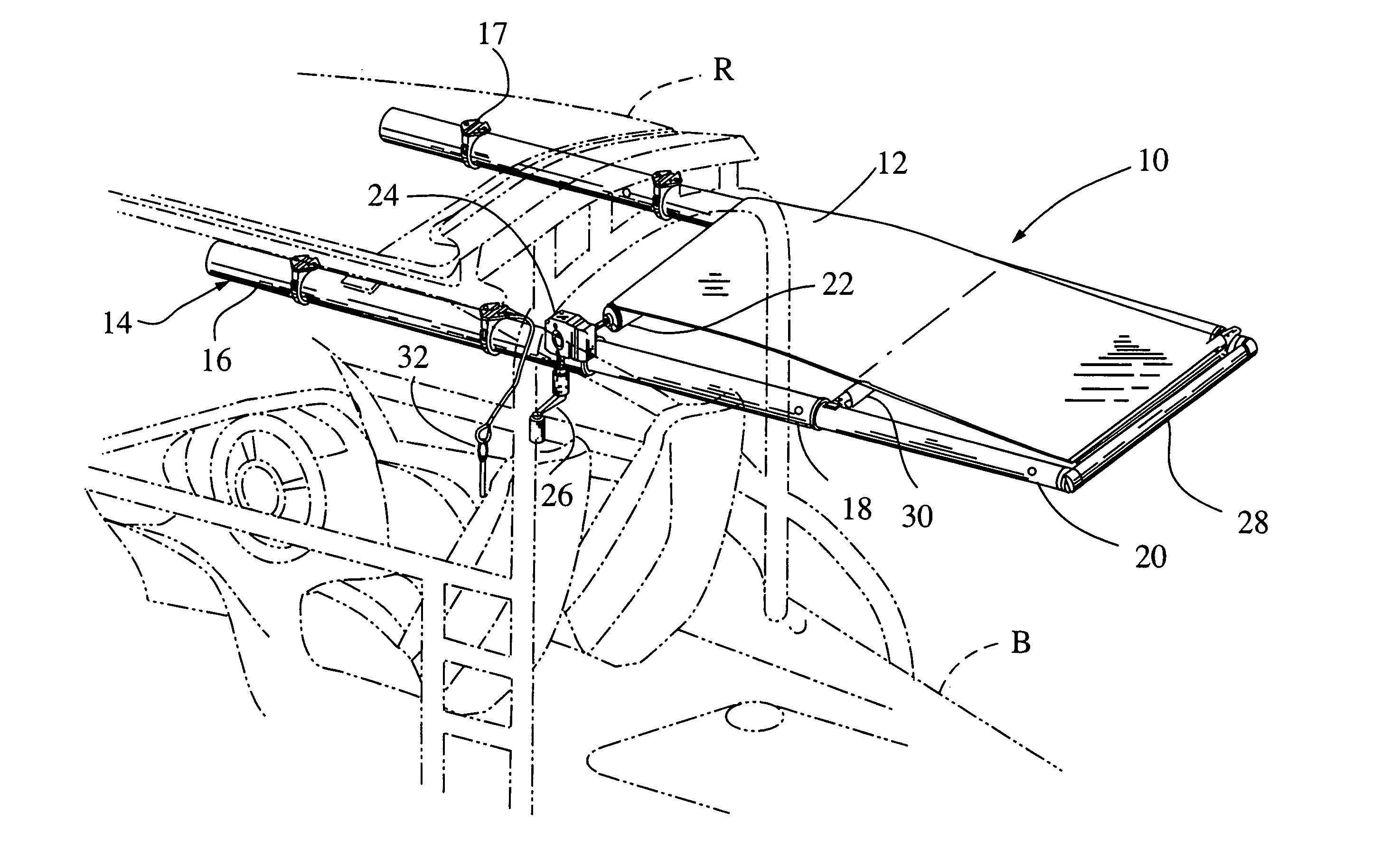
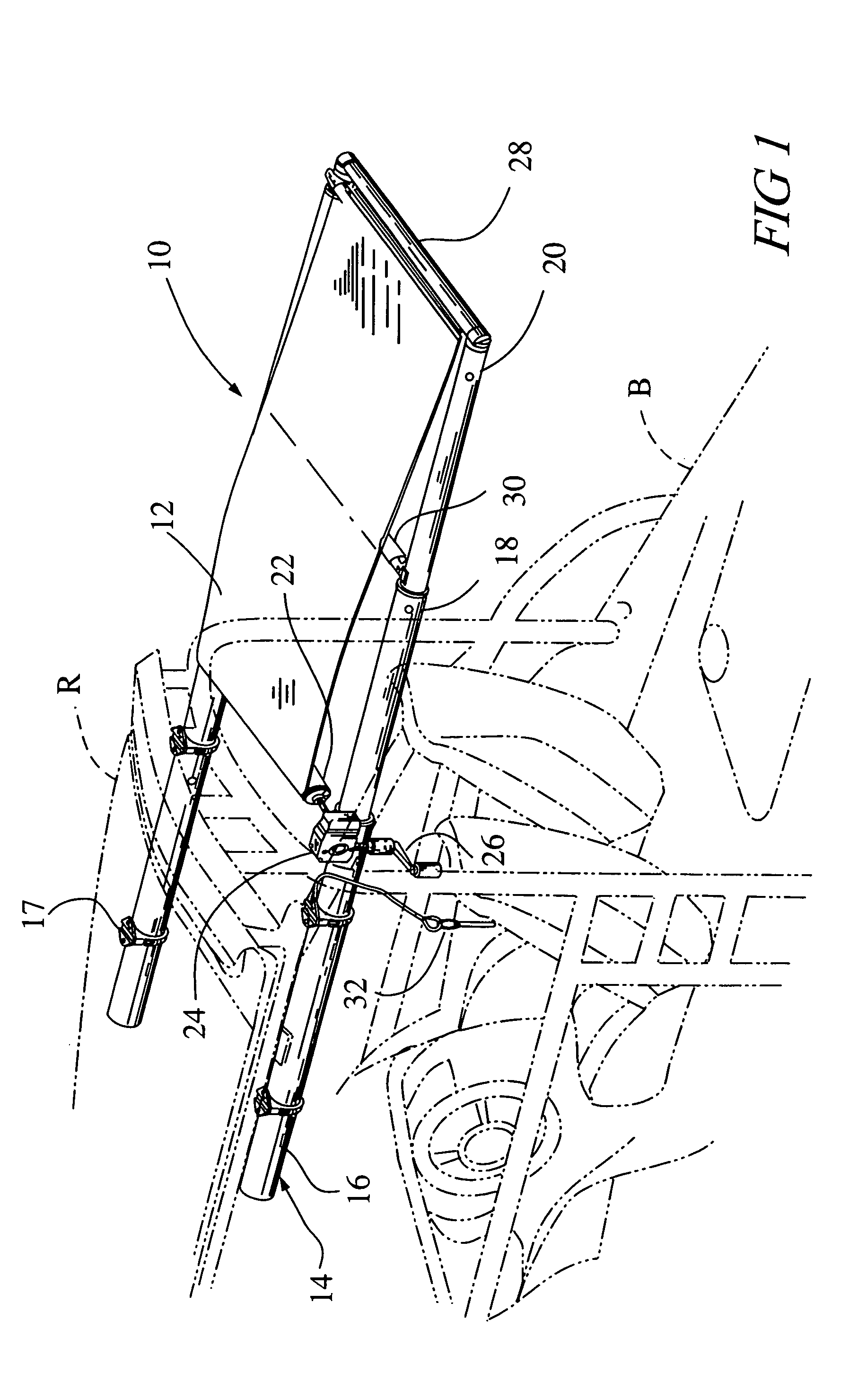
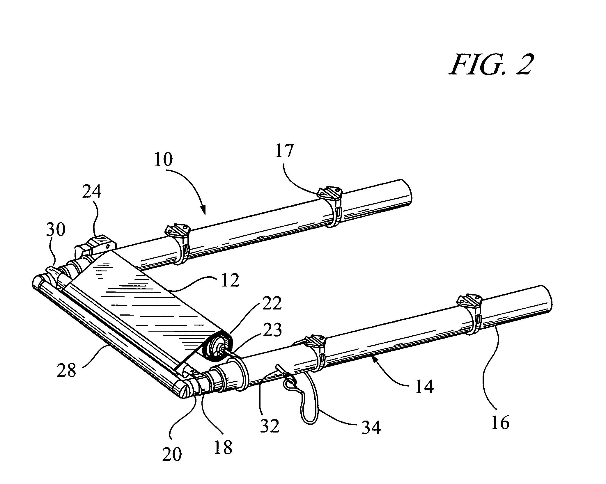
[0021]Referring to the drawings, the following is a list of structural elements of the present canopy deployment system, generally designated 10, and those associated elements shown employed in connection with the present invention:[0022]10 canopy deployment system;[0023]12 canvas;[0024]14 tubular actuator assembly;[0025]16 rearward outer tube;[0026]16a rearward tube hole;[0027]17 mounting clamps;[0028]18 intermediate tube member;[0029]18a intermediate tube hole; [0030]20 forward tube member;[0031]20a forward tube hole; [0032]22 roller member;[0033]23 roller shaft;[0034]24 gear box;[00...


PUM


Abstract

A manually-operated canopy deployment system for mounted attachment onboard recreational boats comprises a pair of spring-loaded tubular actuators telescopically assembled and coupled in parallel alignment to deploy a flexible canvas from a roller member transversely mounted between the actuators with a gear box operatively connected to the roller member to control the canvas deployment. Each actuator assembly includes a rearward outer tube, and separate forward and intermediate interior tubes each fitted with inner end caps and coaxially disposed to move longitudinally within the outer tube, with compression springs separately disposed within the respective tube chambers to apply outbound forces axially upon the inner ends of the respective interior tubes. Forward and intermediate cross bars connected across the interior tubes serve to draw the canvas from the roller member and support canvas deployment, with a pair of loop attachments provided on the surface of the canvas to prevent billowing thereof.

Description

CROSS-REFERENCE TO RELATED APPLICATION[0001]This application is a continuation-in-part of provisional patent application Ser. No. 61 / 396,569 filed May 28, 2010 for Manually-Operated Boat Canopy System.BACKGROUND OF THE INVENTION[0002]The present invention relates to retractable canopy systems for boats, and more particularly to an improved manually-operated canopy deployment system wherein a pair of spring-loaded telescoping tubular actuators are assembled and connected in parallel alignment within a self-supporting framework to deploy a flexible canvas with a gear box to control the telescopic movement of the actuators and provide lightweight and readily mountable sunshade protection on a variety of boat structures.[0003]In recreational boating, the so-called “bimini top” is a convertible cover erected upon the deck of the boat and made to be deployed at an elevation comfortably above the heads of the passengers. Drawing its name from the Bimini islands in the Bahamas where it was ...

Claims


Application Information

Patent Timeline
Patent Type & Authority Patents(United States)
IPC IPC(8): B63B17/00B63B17/02
CPCB63B17/02B63B2221/24
Inventor RUSSIKOFF, RONALD, K.
Owner LIPPERT COMPONENTS MFG INC
Why Eureka
Try Eureka