Vapor chamber having heated protrusion

a technology of vapor chamber and protrusion, which is applied in the direction of lighting and heating equipment, electrical equipment, etc., can solve the problems of increasing the production cost of vapor chamber, increasing the production cost, and bringing the whole heat-absorbing surface into thermal contact with the heat-generating element, so as to prevent the dry-out of working fluid, reduce production costs, and enhance the efficiency of the first wick structure

Inactive Publication Date: 2014-10-14
KUNSHAN JUZHONG ELECTRONICS
View PDF8 Cites 17 Cited by
  • Summary
  • Abstract
  • Description
  • Claims
  • Application Information

AI Technical Summary

Benefits of technology

[0009]The present invention is to provide a vapor chamber having a heated protrusion, in which a wick structure is provided at a position corresponding to the heat-generating element. By this arrangement, the heat-conducting efficiency of the wick structure is increased and the cost is reduced.
[0019]Since the other side of the bottom plate is formed with the accommodating trough corresponding to the heated protrusion, and the first wick structure is disposed in the accommodating trough, the size of the first wick structure can be controlled based on the peripheral dimension of the heat-generating element. Thus, the efficiency of the first wick structure is enhanced greatly, and the production cost is reduced.
[0020]Since the second wick structure has an opening corresponding to the accommodating trough and a plurality of airflow channels in communication with the opening, the vapor-phase working fluid in the first wick structure can rapidly flow through the opening and the airflow channels toward the cover plate, thereby conducting the heat generated by the heat-generating element to the cover plate rapidly.
[0021]Since the cover plate is formed with a plurality of supporting posts, and the second wick structure is provided between the cover plate and the bottom plate, the vapor-phase working fluid flowing toward the cover plate condenses on the cover plate, and then the condensed working fluid rapidly flows back to the first wick structure via the second wick structure and the supporting posts, thereby preventing the dry-out of the working fluid in the first wick structure and increasing the heat-conducting effect of the vapor chamber.
[0022]The bottom plate has an accommodating trough. The cover plate is formed with a plurality of supporting posts at a position corresponding to the accommodating trough. The supporting posts are configured to connect and support between the cover plate and the first wick structure. Thus, the supporting posts serve as a path for allowing the vapor-phase working fluid to flow back to the first wick structure. Further, the supporting posts provide a sufficient strength between the cover plate and the first wick structure, thereby preventing the cover plate from recessing into the accommodating trough.

Problems solved by technology

However, not the whole heat-absorbing surface is brought into thermal contact with the heat-generating element.
Thus, a portion of the wick structure on the inner wall of the heat-absorbing surface not contacting the heat-generating element does not contribute to the heat conduction a lot.
In other words, the remaining wick structure inevitably increases the production cost of the vapor chamber.
Since the thickness of each heat-generating element is different, the conventional vapor chamber having a flat heat-absorbing surface cannot surely contact every heat-generating element.
As a result, several vapor chambers have to be disposed on the printed circuit board to correspond to the respective heat-generating element, which increases the production cost.

Method used


Image

  • Vapor chamber having heated protrusion
  • Vapor chamber having heated protrusion
  • Vapor chamber having heated protrusion

Examples


Embodiment Construction

[0032]The detailed description and technical contents of the present invention will become apparent with the following detailed description accompanied with related drawings. It is noteworthy to point out that the drawings is provided for the illustration purpose only, but not intended for limiting the scope of the present invention.

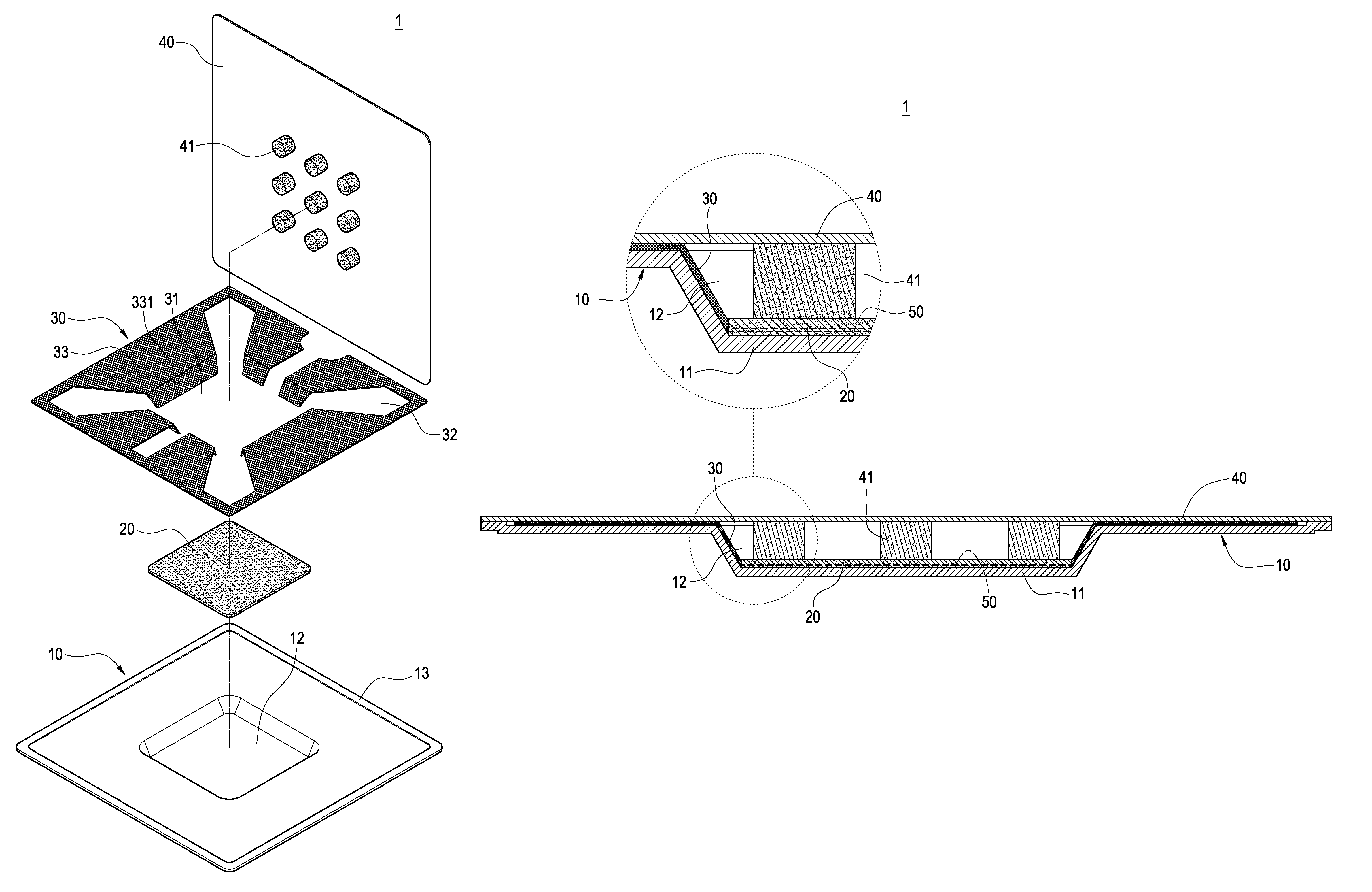
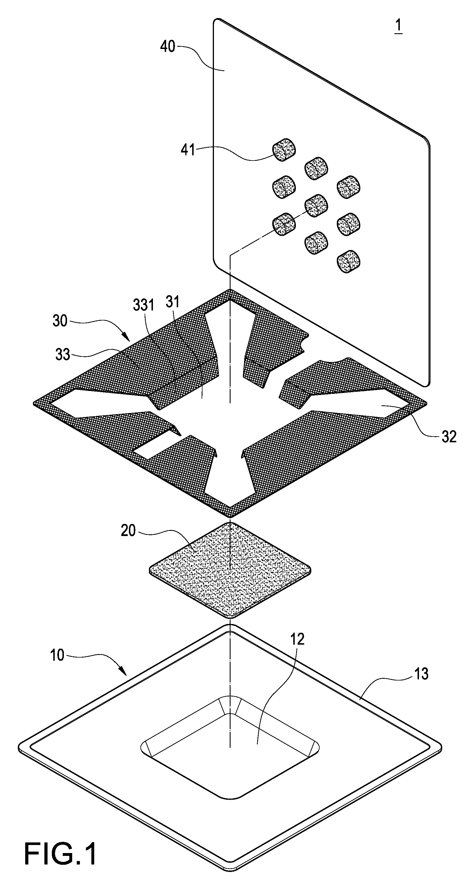
[0033]Please refer to FIGS. 1 to 5. The present invention relates to a vapor chamber 1 having a heated protrusion, which is configured to conduct heat of a heat-generating element 100. The vapor chamber 1 includes a bottom plate 10, a first wick structure 20, a second wick structure 30, a cover plate 40 and a working fluid 50.

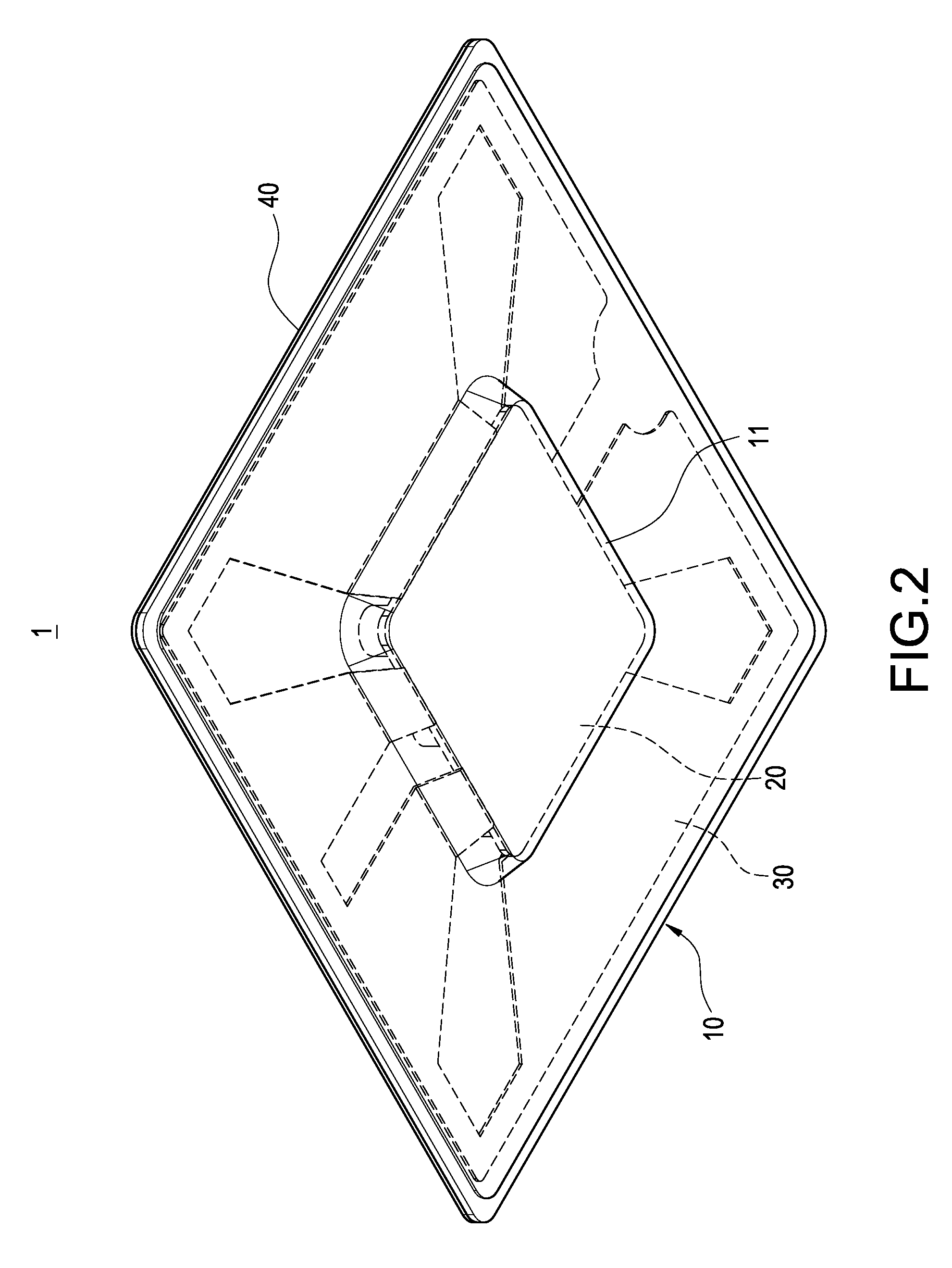
[0034]The bottom plate 10 is made of metallic material. One side of the bottom plate 10 has a heated protrusion 11 brought into thermal contact with the heat-generating element 100 (as shown in FIG. 2). The other side of the bottom plate 10 is formed with an accommodating trough 12 corresponding to the heated protrusion 11. As shown...


PUM


Abstract

A vapor chamber is configured to conduct heat generated by a heat-generating element and includes a bottom plate, a first wick structure, a second wick structure, a cover plate and a working fluid filled between the cover plate and the bottom plate. One side of the bottom plate has a heated protrusion in thermal contact with the heat-generating element, and the other side is formed with an accommodating trough corresponding to the heated protrusion. The first wick structure is provided in the accommodating trough. The second wick structure is disposed on the bottom plate and provided with an opening and a plurality of airflow channels in communication with the opening. The cover plate tightly covers the bottom plate. The supporting posts are sandwiched between the cover plate and the first wick structure. By this arrangement, the mounting and heat-conducting of the heat-generating element can be achieved.

Description

BACKGROUND OF THE INVENTION[0001]1. Field of the Invention[0002]The present invention relates to a vapor chamber, and in particular to a vapor chamber having a heated protrusion.[0003]2. Description of Prior Art[0004]A vapor chamber is a heat-conducting module that is widely used, which includes a flat casing, a working fluid filled in the flat casing, a wick structure formed on inner walls of the flat casing, and a supporting structure provided inside the flat casing. The supporting structure provides a sufficient strength to the flat casing to withstand external pressures, thereby protecting the flat casing from recessing due to the external pressures. In use, one surface of the vapor chamber contacting a heat-generating element is called as a heat-absorbing surface, and the other surface of the vapor chamber away from the heat-generating element is called as a heat-releasing surface. A portion of the working fluid in the vapor chamber adjacent to the heat-absorbing surface absorb...

Claims


Application Information

Patent Timeline
Patent Type & Authority Patents(United States)
IPC IPC(8): F28D15/04F28D15/02
CPCF28D15/0233F28D15/046
Inventor HUANG, YU-PO
Owner KUNSHAN JUZHONG ELECTRONICS
Why Eureka
Try Eureka