Illumination optical system and image projection apparatus
an optical system and optical system technology, applied in the field of illumination optical system and image projection apparatus, can solve the problems of unintentional split light beams that are supposed to be incident on the corresponding lens cells, unnatural split light beams, and increased light loss, so as to reduce the amount of light loss
- Summary
- Abstract
- Description
- Claims
- Application Information
AI Technical Summary
Benefits of technology
Problems solved by technology
Method used
Image

Examples
first embodiment
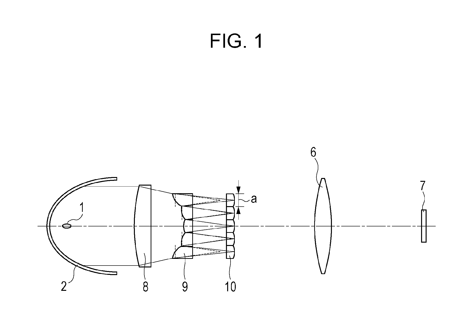
[0028]FIG. 1 is a schematic diagram illustrating an illumination optical system according to a first embodiment of the present invention. FIG. 1 illustrates a light source 1, a parabolic reflector 2, a converging lens 8, a first fly's eye lens (first lens array) 9, a second fly's eye lens (second lens array) 10, a condenser lens (optical element) 6, and a liquid crystal display element (image display element) 7. The first fly's eye lens 9 is formed by arranging rectangular lens cells, which have similar figures to the liquid crystal display element 7, in a matrix. The second fly's eye lens 10 includes multiple lens cells corresponding to the lens cells of the first fly's eye lens 9.
[0029]Light emitted from the light source 1 is reflected by the parabolic reflector 2 and becomes substantially parallel light beams. The substantially parallel light beams are incident on the converging lens 8 and changed into converged light by the converging lens 8. The converged light is incident on t...
second embodiment
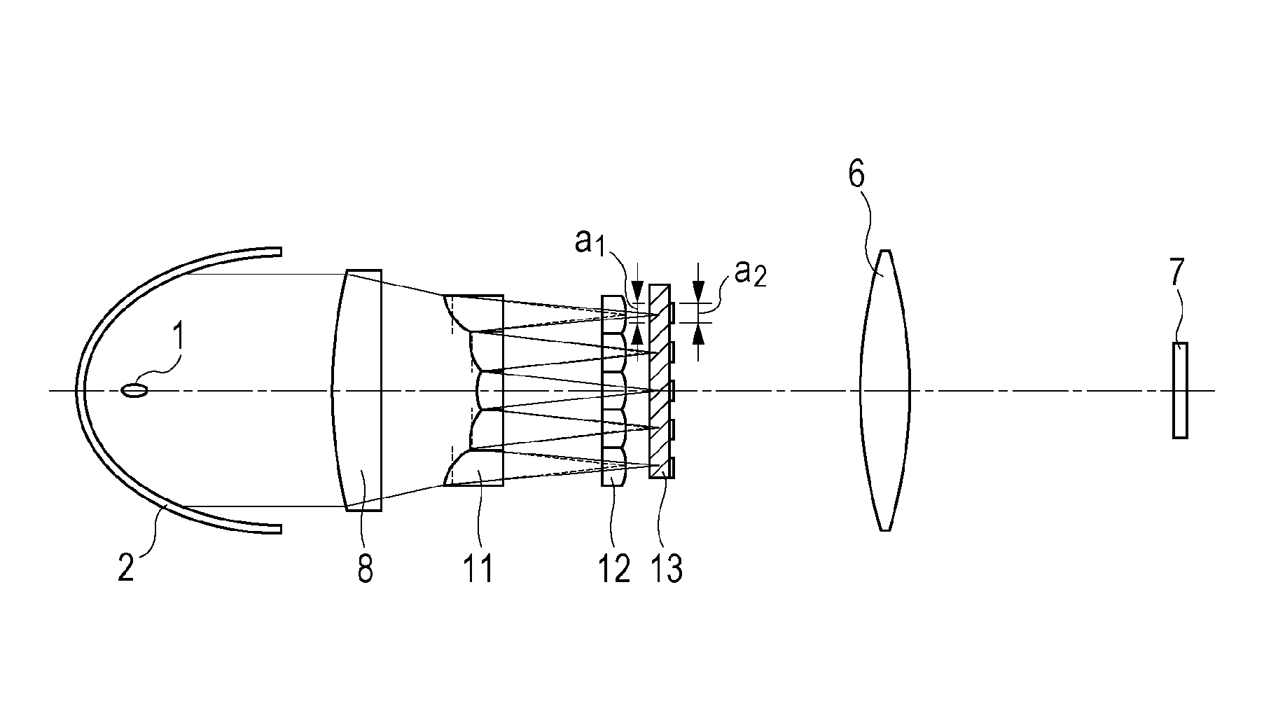
[0061]FIG. 5 is a schematic diagram illustrating an illumination optical system according to a second embodiment of the present invention. Light emitted from a light source 1 is reflected by a parabolic reflector 2 and becomes substantially parallel light beams. The substantially parallel light beams are incident on a converging lens 8 and changed into converged light by the converging lens 8. The converged light is incident on a first fly's eye lens 11 formed by arranging rectangular lens cells, which have similar figures to the liquid crystal display element 7, in a matrix.
[0062]Lens cells constituting the first fly's eye lens 11 are decentered, and the decentering amounts increase stepwise from a lens cell near the optical axis toward a lens cell in a peripheral portion. Furthermore, the thicknesses of the lens cells increase stepwise the closer a lens cell is disposed to a peripheral portion so that the curved surfaces of the lens cells are substantially continuous with one anot...
third embodiment
[0078]FIGS. 7A and 7B illustrate schematic diagrams of an illumination optical system according to a third embodiment of the present invention. FIG. 7A is a schematic diagram of a first cross section (taken in the X-Z directions in the drawing) and FIG. 7B is a schematic diagram of a second cross section (taken in the Y-Z directions in the drawing). The first and second cross sections are both taken along the optical axis direction and are perpendicular to each other.
[0079]Light emitted from a light source 1 is reflected by a parabolic reflector 2 and becomes substantially parallel light beams. The substantially parallel light beams are incident on a converging lens 8 and changed into converged light by the converging lens 8. The converged light is incident on a first fly's eye lens 14.
[0080]Lens cells constituting the first fly's eye lens 14 are decentered, and the decentering amounts increase stepwise from a lens cell near the optical axis toward a lens cell in a peripheral portio...
PUM
 Abstract
Description
Claims
Application Information
 - R&D Engineer
- R&D Manager
- IP Professional
- Industry Leading Data Capabilities
- Powerful AI technology
- Patent DNA Extraction
Browse by: Latest US Patents, China's latest patents, Technical Efficacy Thesaurus, Application Domain, Technology Topic.
© 2024 PatSnap. All rights reserved.Legal|Privacy policy|Modern Slavery Act Transparency Statement|Sitemap