
Phase modulator for modulating light interacting with the phase modulator

a phase modulator and light interacting technology, applied in the field of phase modulators, can solve the problem of disadvantageous reduction of the transmittance of the phase modulator

Active Publication Date: 2014-10-14
SEEREAL TECHNOLOGIES
View PDF13 Cites 6 Cited by
  • Summary
  • Abstract
  • Description
  • Claims
  • Application Information

AI Technical Summary

Benefits of technology

The patent describes a new method for controlling the orientation of molecules in a way that allows for improved performance of a phase modulator. Unlike previous methods, this method can use common industry methods to fix the molecule orientation, which allows for easier manufacturing and control. Additionally, this method allows for improved switching speed and high efficiency of deflection.

Problems solved by technology

However, the transmittance of the phase modulator is disadvantageously reduced due to the different thickness then.

Method used


Image

  • Phase modulator for modulating light interacting with the phase modulator
  • Phase modulator for modulating light interacting with the phase modulator
  • Phase modulator for modulating light interacting with the phase modulator

Examples


Embodiment Construction

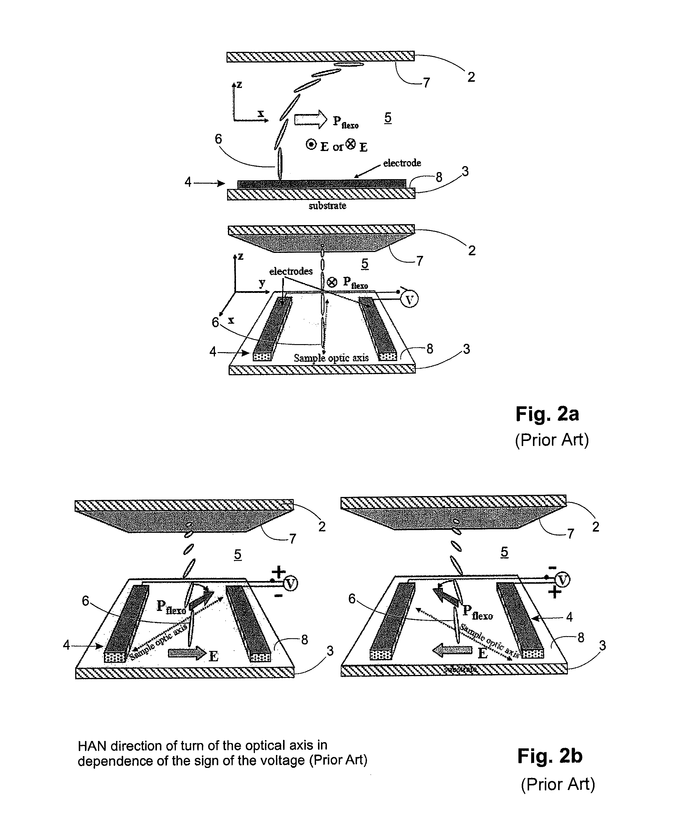
[0046]FIG. 2 illustrates the principle of a HAN cell according to the prior art which is based on the flexo-electric effect. In the HAN cell, the LC molecules 6 which are situated near one surface 7 are aligned parallel to the surface 7, and those which are situated near the other surface 8 are aligned perpendicular to the surface 8. If the liquid crystal molecules 6 have a suitable shape, then this molecule orientation will cause flexo-electric polarisation. The direction of rotation of the optical axis of a liquid crystal molecule 6 will then depend on the sign of the applied voltage V.

[0047]FIG. 2a shows a sectional view (top) and a perspective side view (bottom) which illustrate a detail of a HAN cell where the electrode arrangement 4 is not activated. FIG. 2b shows the same HAN cell of FIG. 2a again. A first active operational situation is shown on the left, where Pflexo and the optical axis of the liquid crystal layer 5 are turned clockwise. A second active operational situati...


PUM

PropertyMeasurementUnit
molecule rotation anglesaaaaaaaaaa
grating periodaaaaaaaaaa

Abstract

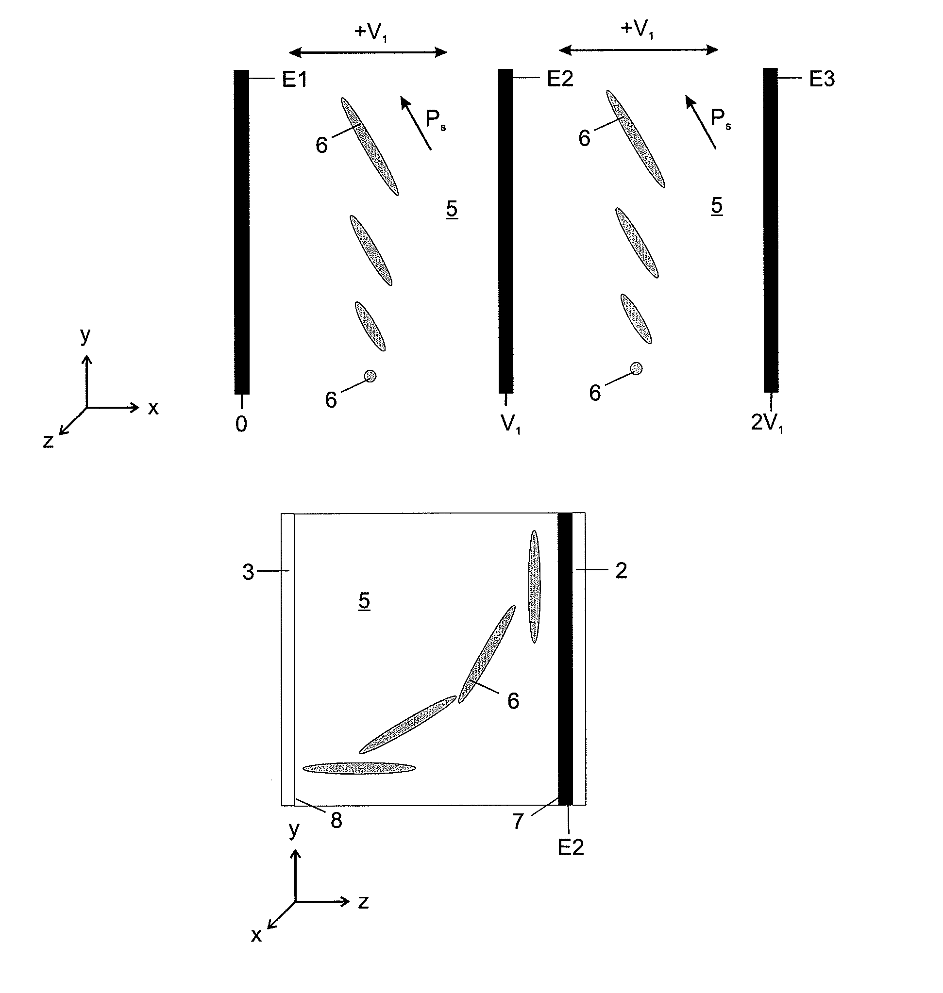
A phase modulator for the modulation of the phase of circular polarised light which interacts with the phase modulator. The phase modulator has a first and a second substrate, an electrode arrangement and a liquid crystal layer with liquid crystal molecules. The first substrate is disposed adjacent to the second substrate. The liquid crystal layer is disposed between the two substrates. The first substrate has a first surface, and the second substrate has a second surface. The liquid crystal molecules situated next to the first surface are oriented substantially parallel to the first surface. The liquid crystal molecules situated next to the second surface are oriented substantially perpendicular to the second surface. An in-plane component of the liquid crystal molecule orientation can be set within an angular range of about 180°, e.g. between 90° and +90° related to a specifiable central orientation.

Description

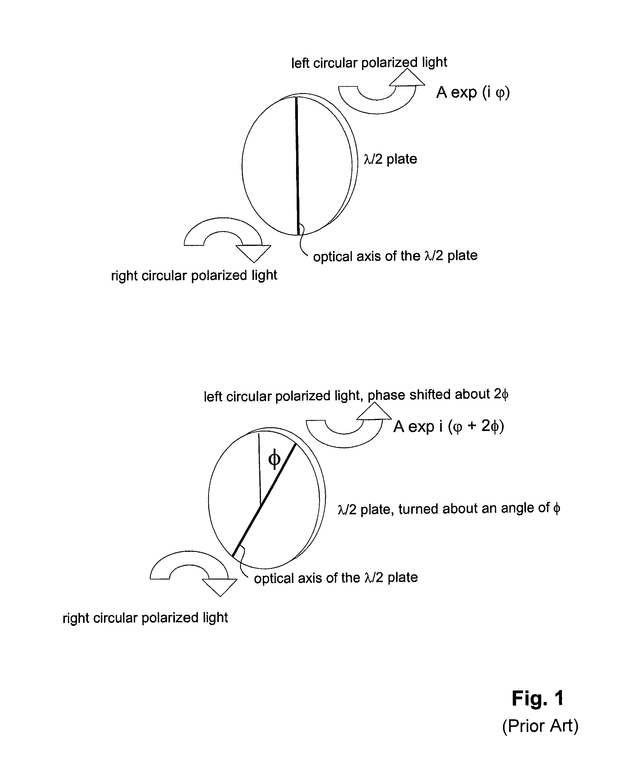
CROSS REFERENCE TO RELATED APPLICATIONS[0001]This application claims the priority of PCT / EP2010 / 068582, filed on Dec. 1, 2010, which claims priority to German Application No. 10 2009 047371.8, filed Dec. 1, 2009, the entire contents of all of which are hereby incorporated in total by reference.BACKGROUND OF THE INVENTION[0002]The present invention relates to a phase modulator for the modulation of the phase of circular polarised light which interacts with the phase modulator. The present invention further relates to a display for the presentation of two-dimensional and / or three-dimensional image contents.[0003]According to S. Pancharatnam, Proc. Ind. Acad. Sci., p. 137, 1955, the phase of light can be modulated in that circular polarised light is used and that a λ / 2 plate is rotated in its plane. This is shown schematically in FIG. 1. Circular polarised light falls on a λ / 2 plate. The direction of rotation of the circular polarised light changes. In addition, a phase occurs which de...

Claims


Application Information

Patent Timeline
Patent Type & Authority Patents(United States)
IPC IPC(8): G02F1/1335G02F1/1343G02B30/00G02F1/139G02F1/29
CPCG02F1/1393G02F1/292G02F1/134363G02F2001/133541G02F1/1337G02B27/22G02F1/133528G02B30/00G02F1/133541
Inventor KROLL, BOLEISTER, NORBERT
Owner SEEREAL TECHNOLOGIES
Learn More