Cabin air compressor motor cooling

a technology for air compressors and motors, applied in the field of cabin air compressor motor cooling, can solve the problems of reducing the performance of cac, reducing the cooling flow of typically exhausting the air to the outside, so as to increase the cooling flow across the cabin air compressor motor

Active Publication Date: 2014-10-21
HAMILTON SUNDSTRAND CORP
View PDF15 Cites 8 Cited by
  • Summary
  • Abstract
  • Description
  • Claims
  • Application Information

AI Technical Summary

Benefits of technology

[0003]According to one aspect of the invention, a cabin air compressor assembly includes a cabin air compressor disposed at a compressor inlet and a cabin air compressor motor operably connected to the cabin air compressor. At least one cooling flow inlet is located at a first end of the cabin air compressor motor substantially opposite a second end whereat the cabin air compressor is located. The cooling flow inlet is configured to direct a cooling flow across the cabin air compressor motor. A blower is operably connected to the cabin air compressor and is configured to urge a cooling flow from across the cabin air compressor motor toward a cooling flow outlet, thereby increasing the cooling flow across the cabin air compressor motor.

Problems solved by technology

After passing through the cabin, the air is typically exhausted to the outside.
The flow of cooling air and thus the performance of the electric motor and CAC is typically limited by the pressure drop from the CAC inlet to the ram air system.
Such a limitation may result in reduced performance of the CAC.

Method used


Image

  • Cabin air compressor motor cooling
  • Cabin air compressor motor cooling
  • Cabin air compressor motor cooling

Examples


Embodiment Construction

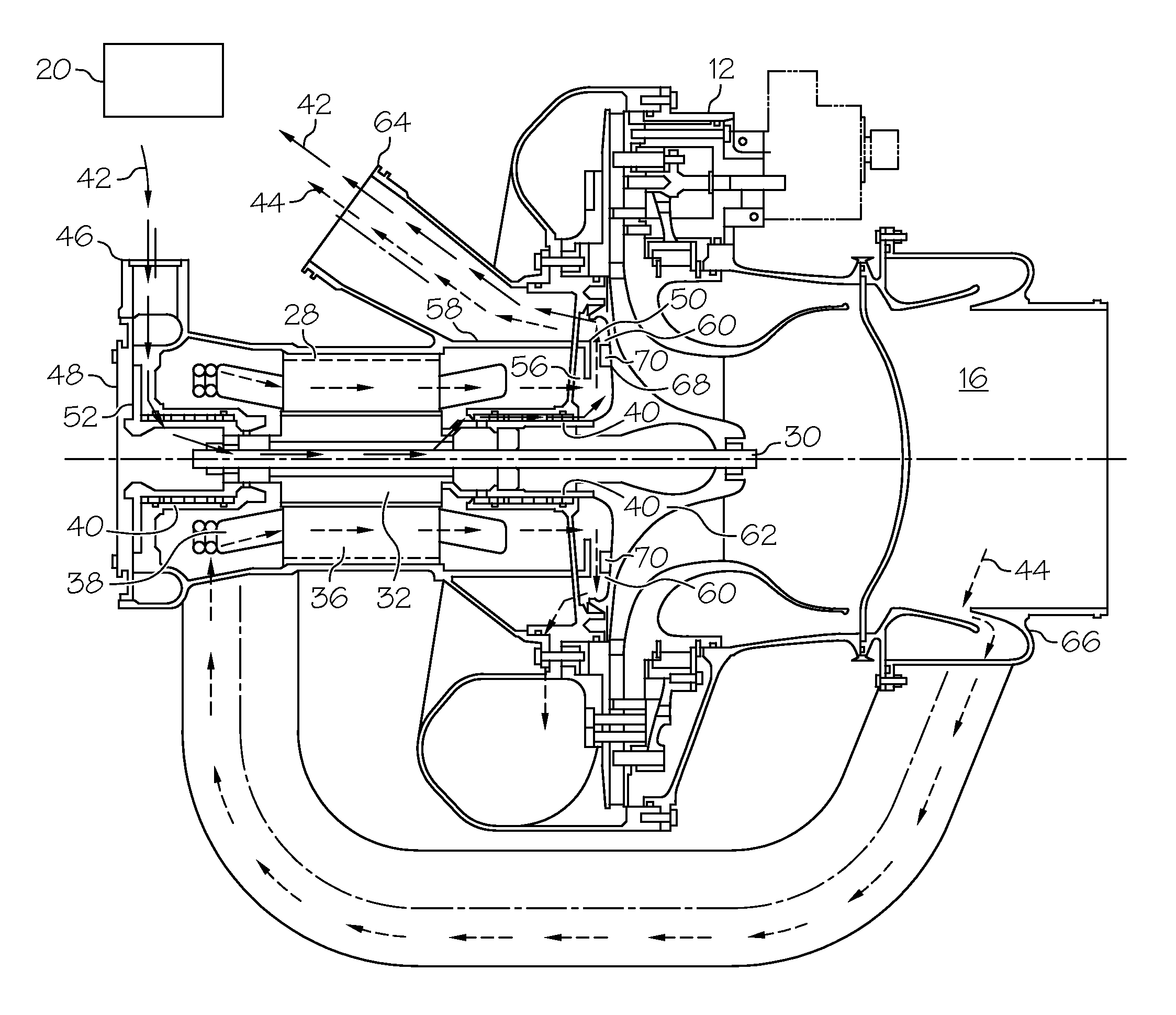
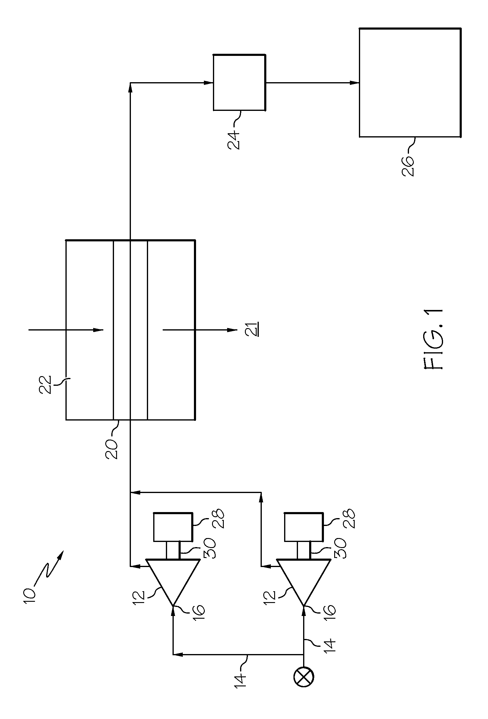
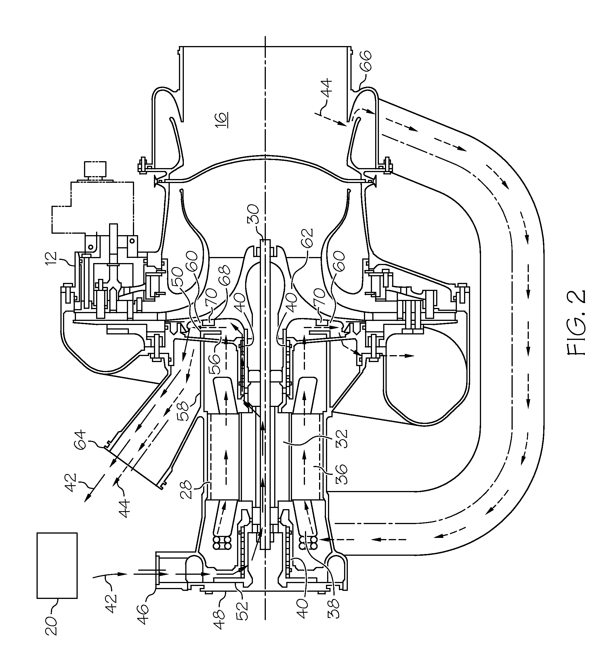
[0007]Shown in FIG. 1 is a schematic of the pertinent portion of an environmental control system (ECS) 10 for an aircraft. The ECS 10 includes one or more cabin air compressors (CACs) 12, which in some embodiments are centrifugal compressors. An outside airflow 14, or air from another source, flows into the CAC 12 at a compressor inlet 16. The CAC 12 compresses the airflow 14 and urges the airflow 14 from the compressor inlet 16 to a heat exchanger inlet 20, which in some embodiments may be part of a ram system 22, and evaporator 24 and then delivered to an aircraft cabin 26. Each CAC 12 is driven by a CAC motor 28 operably connected to the CAC 12 via a CAC shaft 30.

[0008]Referring now to FIG. 2, the CAC motor 28 is an electric motor having a rotor 32 rotatably located at the CAC shaft 30, and a stator 36 having a plurality of stator windings 38 disposed radially outboard of the rotor 32. The CAC motor 28 also includes one or more bearings 40 disposed at the CAC shaft 30. To prevent...


PUM


Abstract

A cabin air compressor assembly includes a cabin air compressor disposed at a compressor inlet and a cabin air compressor motor operably connected to the cabin air compressor. At least one cooling flow inlet is located at a first end of the cabin air compressor motor substantially opposite a second end whereat the cabin air compressor is located. The cooling flow inlet is configured to direct a cooling flow across the cabin air compressor motor. A blower is operably connected to the cabin air compressor and is configured to urge a cooling flow from across the cabin air compressor motor toward a cooling flow outlet, thereby increasing the cooling flow across the cabin air compressor motor.

Description

BACKGROUND OF THE INVENTION[0001]The subject matter disclosed herein relates to aircraft environmental control. More specifically, the subject disclosure relates to cooling of a cabin air compressor motor for an aircraft environmental control system.[0002]Environmental control systems (ECS) are utilized on various types of aircraft for several purposes, such as in cooling systems for the aircraft. For example, components of the ECS may be utilized to remove heat from various aircraft lubrication and electrical systems and / or used to condition aircraft cabin air. The cabin air conditioner includes one or more cabin air compressors (CACs) which compress air entering the system, from an outside source or from a ram air system. The compressed air is delivered to an environmental control system to bring it to a desired temperature then delivered to the aircraft cabin. After passing through the cabin, the air is typically exhausted to the outside. The CACs are typically driven by air-cool...

Claims


Application Information

Patent Timeline
Patent Type & Authority Patents(United States)
IPC IPC(8): F25D9/00B64D13/06F04D29/58
CPCF04D29/5806F04D29/584B64D13/06F04D25/06F04D29/056B64D2013/0644Y02T50/50
Inventor HIPSKY, HAROLD, W.
Owner HAMILTON SUNDSTRAND CORP
Why Eureka
Try Eureka