Rigid aircraft pylon fitted with a rib extension for taking up the moment in the lengthways direction

Active Publication Date: 2014-10-21
AIRBUS OPERATIONS SAS
View PDF6 Cites 6 Cited by
  • Summary
  • Abstract
  • Description
  • Claims
  • Application Information

AI Technical Summary

Benefits of technology

[0009]Thus, the invention provides an original solution enabling the bending moment associated with the engine assembly, exerted in the lengthways direction, to be transmitted, when this unit is mounted laterally on the structure of the aircraft, i.e. preferably on its fuselage and/or on a lateral extension of this fuselage. Indeed, the first and second attachments are presently designed to transmit the moment exerted in the lengthways direction, and are separated from one another in the line of separation between the rigid structure and the turbine engine, where this direction is also the line of separation between the fuselage of the aircraft and this same turbine engine. In this direction, it is easily possible to separate both attachments by a substantial distance

Problems solved by technology

When such a position is chosen one of the difficulties in designing the mounting pylon lies in transmitting the moment exerted in the lengthways direction where the engine assembly is attached to the aircraft's fuselage.
However, given the extremely high intensity of this bending moment which is exerted in the lengthways direction, it is necessary to over-dimensi

Method used


Image

  • Rigid aircraft pylon fitted with a rib extension for taking up the moment in the lengthways direction
  • Rigid aircraft pylon fitted with a rib extension for taking up the moment in the lengthways direction
  • Rigid aircraft pylon fitted with a rib extension for taking up the moment in the lengthways direction

Examples


Example

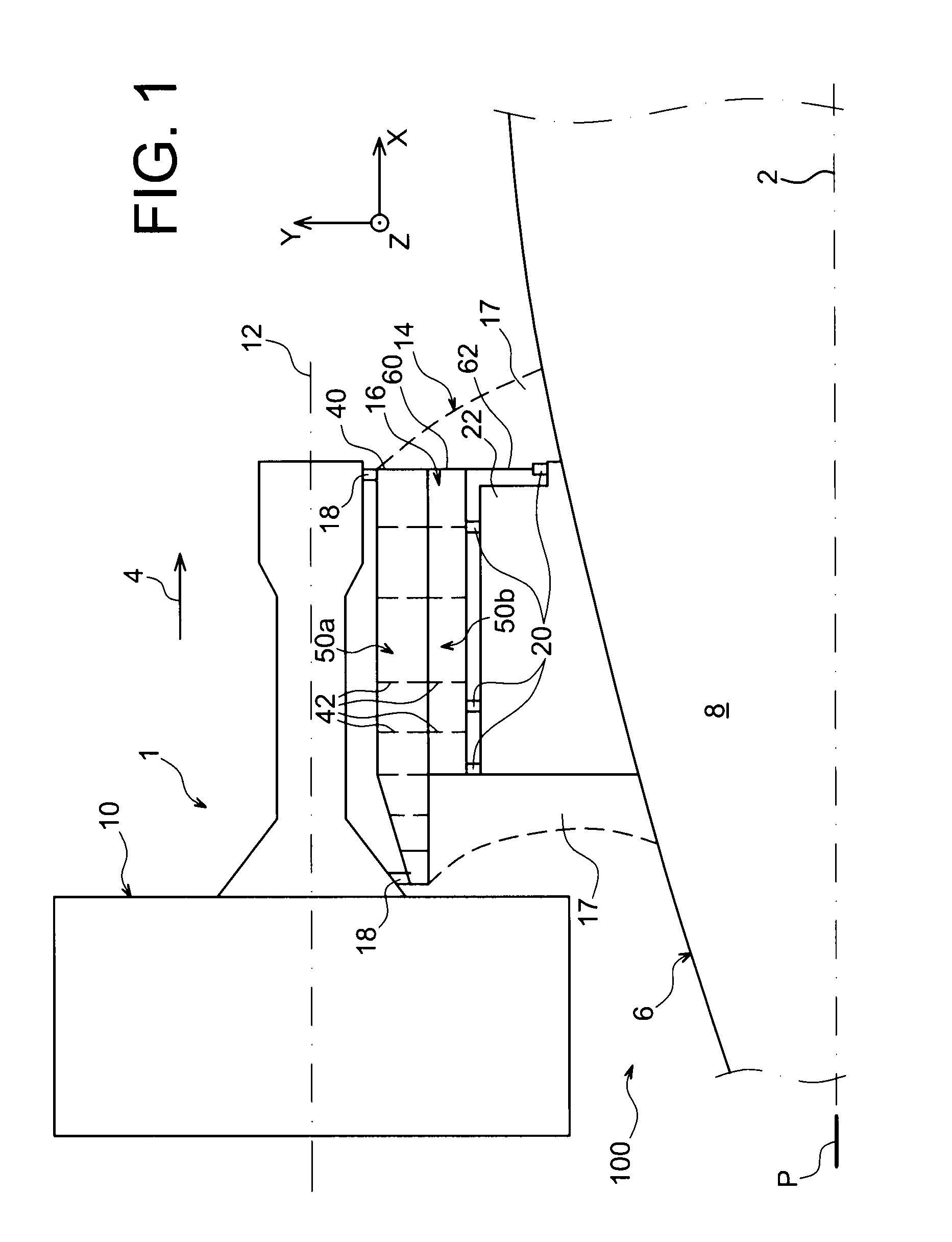
[0029]With reference to FIG. 1, a rear part 100 of an aircraft can be seen including an engine assembly having the form of a preferred embodiment of the present invention.

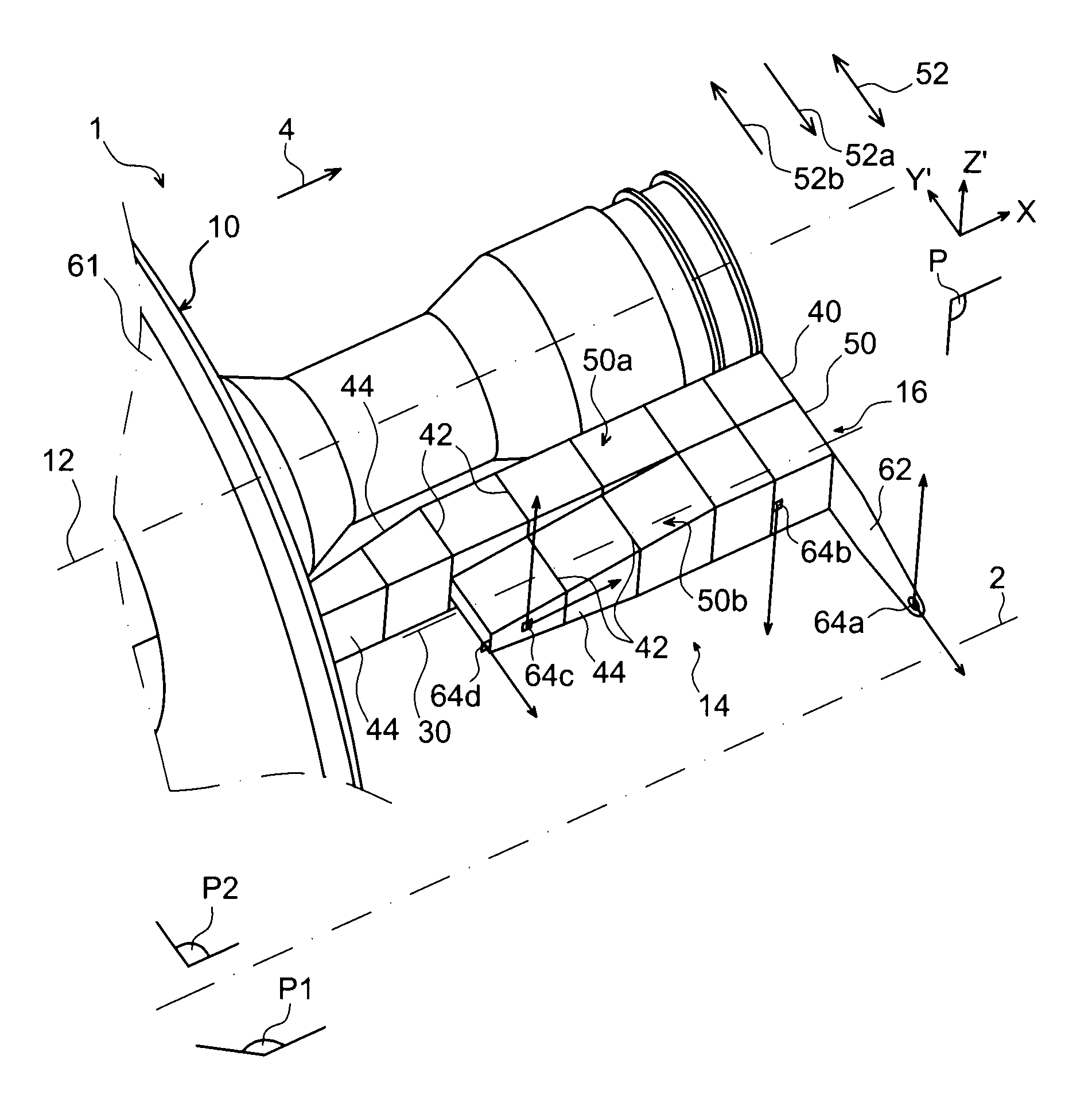
[0030]In the whole of the following description, by convention, the lengthways direction of the aircraft which is parallel to a lengthways axis of this aircraft is called X. In addition, the direction aligned transversely relative to the aircraft is called Y, and the vertical direction or direction of the height is called Z, and these three directions X, Y and Z are mutually orthogonal.

[0031]In addition, the terms “front” and “rear” must be considered relative to the forward direction of the aircraft imparted due to the thrust exerted by the engines, and this direction is represented schematically by the arrow 4.

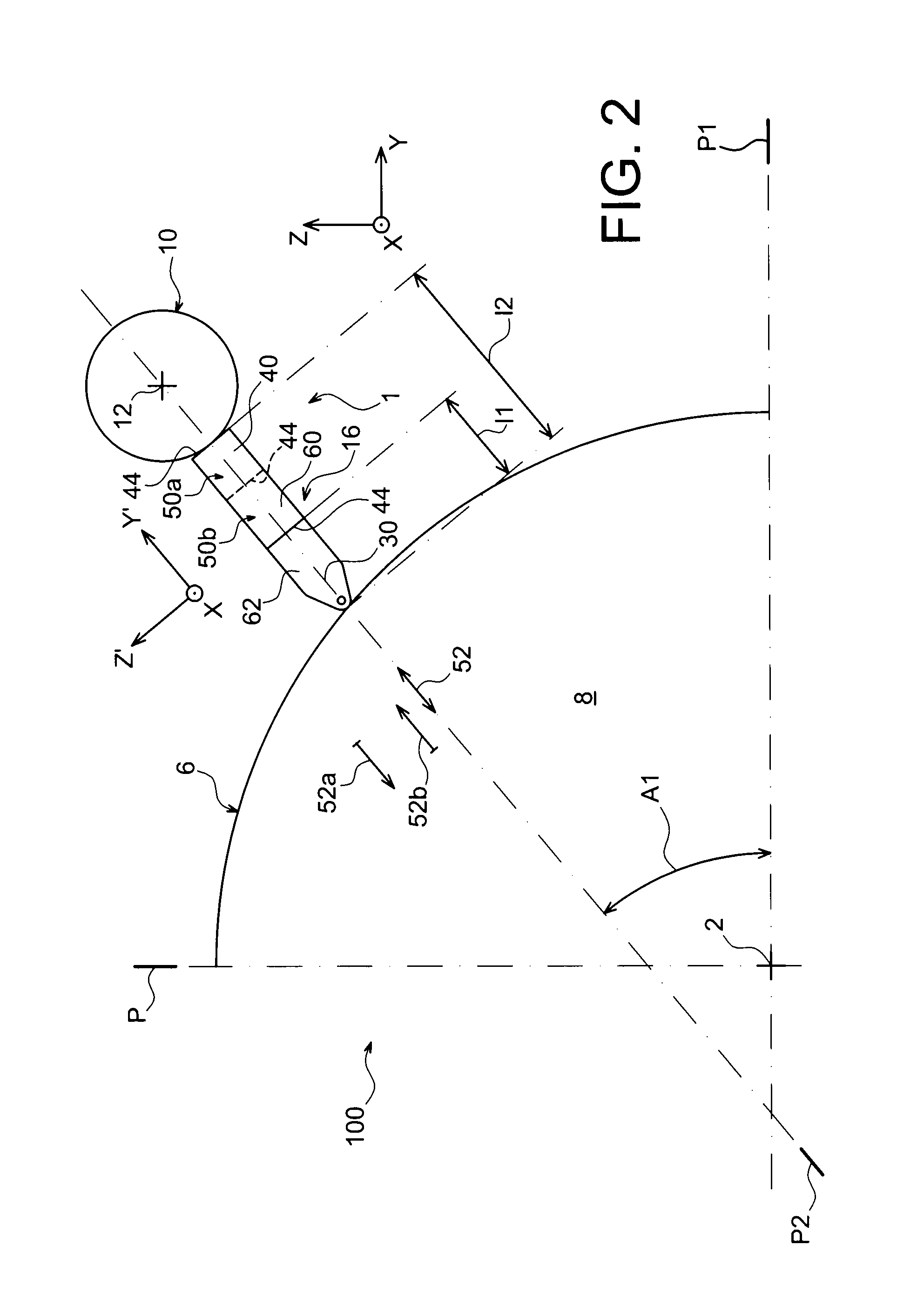
[0032]Overall, the rear part 100 includes a fuselage 6, of which only a portion of the left-hand part has been represented. The transverse section of this fuselage is roughly circular, elliptical or similar...


PUM


Abstract

An engine assembly for an aircraft, including a rigid structure including a box rib extension protruding from a box of the structure, in a line of separation, towards a fuselage of the aircraft. The extension supports a first attachment in a position separating it from a second attachment in the line of separation. The first and second attachments enable the moment being exerted in a lengthways direction of the turbine engine to be transmitted jointly.

Description

BACKGROUND OF THE INVENTION[0001]I. Field of the Invention[0002]The present invention relates in a general sense to an aircraft engine assembly, particularly of the type intended to be mounted laterally on a rear part of the aircraft.[0003]II. Description of Related Art[0004]When such a position is chosen one of the difficulties in designing the mounting pylon lies in transmitting the moment exerted in the lengthways direction where the engine assembly is attached to the aircraft's fuselage. This moment results, indeed, from a high load applied vertically to the centre of gravity of the engine assembly, which is positioned laterally offset from the fuselage on to which this unit is attached.[0005]Generally, the fasteners interposed between the rigid structure of the mounting pylon and the structure of the aircraft are designed such that this bending moment is transmitted with two separate attachments, each transmitting radial loads, and spaced relative to one another in the tangenti...

Claims


Application Information

Patent Timeline
IPC IPC(8): B64D27/26B64D27/20B64D27/14
CPCB64D2027/266B64D27/26B64D27/14
Inventor MARCHE, JACQUES, HERVE
Owner AIRBUS OPERATIONS SAS
Why Eureka
Try Eureka