Screw capable of rapidly drilling and cutting

a screw and fastener technology, applied in the direction of threaded fasteners, screws, fastening means, etc., can solve the problems of affecting the speed of screwing, the inability to timely expel debris, and the inability to completely sever fibers contained in objects, so as to reduce the screwing torque and accelerate the screwing speed. , the effect of rapid expulsion of cutting debris

Active Publication Date: 2014-10-21
TAIWAN SHAN YIN INT CO LTD
View PDF11 Cites 10 Cited by
  • Summary
  • Abstract
  • Description
  • Claims
  • Application Information

AI Technical Summary

Benefits of technology

[0007]It is therefore the purpose of this invention to provide a screw that is capable of rapidly drilling and cutting so as to promote the screwing speed and the debris-guiding effect but decrease the screwing torque, thereby beneficial for succeeding operation.
[0016]Accordingly, the positioning member helps the screw stably stand on a screwing object, which allows the sub cutting edges to provide a succeeding scraping effect in time of drilling. Further, the cutting planes guide cutting debris to smoothly enter the channels between the threaded units so as to rapidly expel the cutting debris therefrom. Thereby, the cutting debris does not pile into the vacancy of the threaded units, so that the screwing torque could be decreased but the screwing speed could be enhanced. Moreover, the screw is favorably embedded in a screwing object without any protrudent part. Therefore, such even screwing object is beneficial to be further fastened.

Problems solved by technology

Thus, it is difficult to completely sever fibers contained in the object 2.
As a result, the debris can not be timely expelled, and the heaped debris incurs an increasing resistance on the screw 1.
Such abnormal operation is unbeneficial for further fastening.

Method used


Image

  • Screw capable of rapidly drilling and cutting
  • Screw capable of rapidly drilling and cutting
  • Screw capable of rapidly drilling and cutting

Examples


Embodiment Construction

[0027]Wherever possible, the same reference numbers are used in the drawings and the description to refer to the same or like parts.

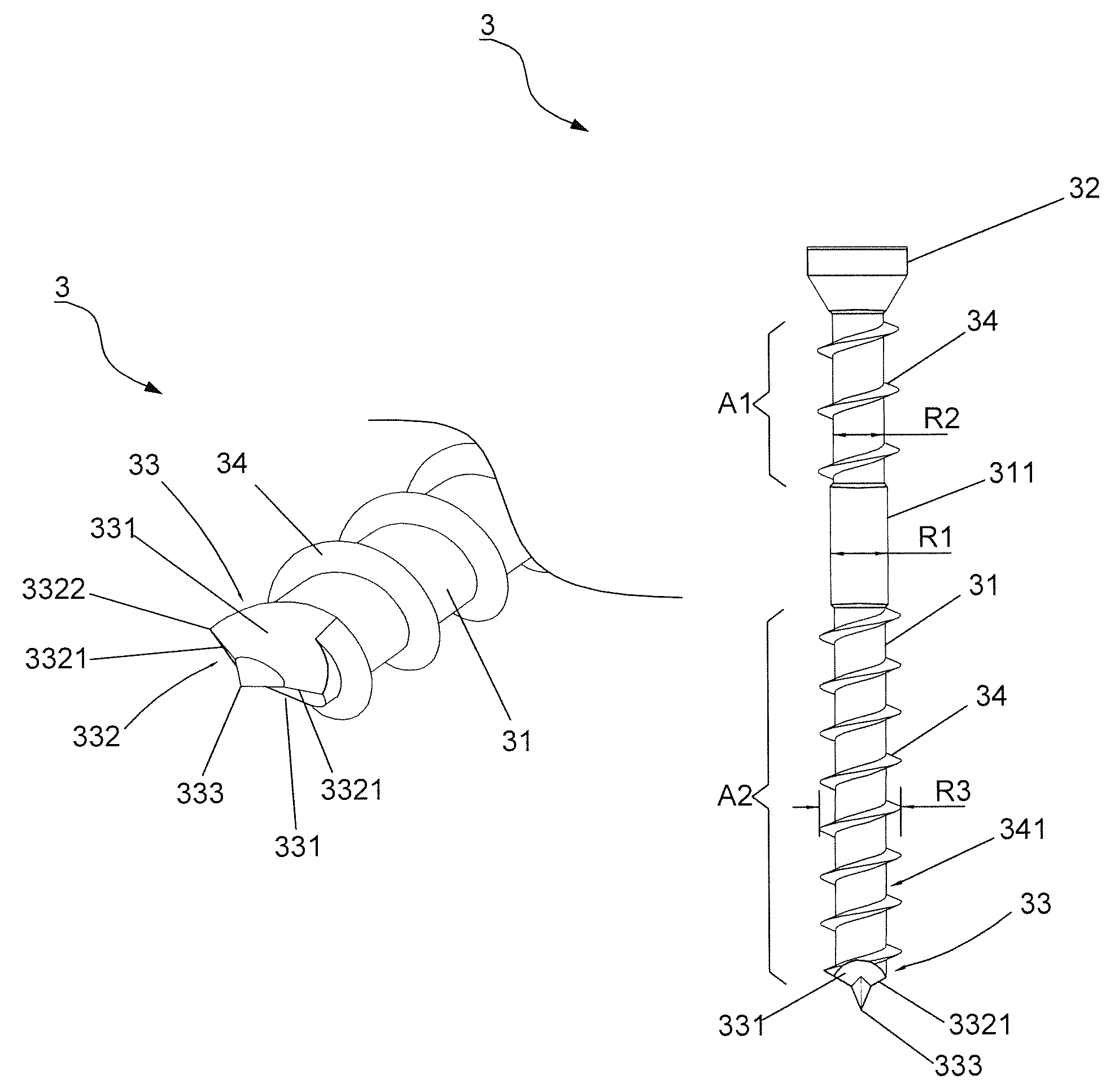
[0028]Referring to FIGS. 3 and 4, a first preferred embodiment of the present invention is shown. In order to clearly show the features of the screw 3, the screw 3 in this figure and in the following embodiments is presented by one side. A screw 3 comprises a shank 31, a head 32 disposed at one end of the shank 31, a drilling portion 33 disposed at the other end of the shank 31, and a plurality of threaded units 34 surroundingly disposed around the shank 31. Wherein, a first guiding channel 341 is defined amid the threaded units 34.

[0029]Further, two inclined cutting planes 331 are convergently formed on the drilling portion 33, and a cutting edge 332 is formed on the connective cutting planes 331. Additionally, a tapered positioning member 333 is integrally bulged outwards from the convergence of the cutting planes 331 to structure a tapered unit for d...


PUM

PropertyMeasurementUnit
included angleaaaaaaaaaa
included angle θ1aaaaaaaaaa
inclined angleaaaaaaaaaa

Abstract

A screw capable of drilling and cutting includes two inclined cutting planes with a cutting edge formed on a convergence of the cutting planes. A tapered positioning member extends from the convergence of the cutting planes, where the cutting edge is divided into dual sub cutting edges by means of the positioning member. Each sub cutting edge has an inclined angle. An included angle included by the sub cutting edges is smaller than 180 degrees. Threads spiral on a shank and extend to the sub cutting edges. Setting the positioning member against on an object permits a steady performance during the first stage of screwing. Subsequently, the sub cutting edges provides a scraping effect on the object during drilling. Torque is reduced and drilling speed is promoted.

Description

BACKGROUND OF THE INVENTION[0001]1. Field of the Invention[0002]The present invention relates to a fastener design, particularly to a screw capable of rapidly drilling and cutting.[0003]2. Description of the Related Art[0004]Referring to FIG. 1, a conventional screw 1 comprises a shank portion 11, a head portion 12 disposed at one end of the shank portion 11, a drilling portion 13 disposed at the other end of the shank portion 11, and a plurality of threaded units 14 spirally disposed around the shank portion 11. Wherein, the drilling portion 13 is formed into a tapered end. Thus, the screw 1 directly enters an object 2 via the tapered drilling portion 13, and the following threaded units 14 continue entering the object 2 so as to achieve a fastening effect.[0005]Afore screw 1 might be smoothly fastened into the object 2 (such as plywood) by means of the drilling portion 13 piercing the object 2. However, in practice, the object 2 is forcedly pierced by the tapered drilling portion ...

Claims


Application Information

Patent Timeline
Patent Type & Authority Patents(United States)
IPC IPC(8): F16B25/10
CPCF16B25/0063F16B25/0015F16B25/0084F16B25/0052F16B25/0068
Inventor SU, KOU-TSAIRSU, YU-JUNG
Owner TAIWAN SHAN YIN INT CO LTD
Why Eureka
Try Eureka