Coil component

a technology of coil and component, applied in the direction of coil, transformer/inductance details, electrical equipment, etc., can solve the problems of coil component, eddy current, eddy current may be caused,

Active Publication Date: 2014-10-21
TDK CORPARATION +1
View PDF7 Cites 2 Cited by
  • Summary
  • Abstract
  • Description
  • Claims
  • Application Information

AI Technical Summary

Benefits of technology

[0008]The present invention has been made by considering the above circumstances, and a purpose of the present invention is to provide a coil component which is possible to be thinner with less leakage flux toward upward and downward directions, and to sustain a good insulation.
[0010]The coil component according to the present invention, distance between outer perimeter edge of the primary coil and inner perimeter edge of the secondary coil varies along circumferential direction. Therefore, according to the coil component of the present invention, leading of wire from primary coil can be performed by using an area where distance between outer perimeter edge of primary coil and inner perimeter edge of secondary coil is large. Therefore, although a coil component according to the present invention is a double structure wherein secondary coil goes around outer circumference of the primary coil, it provides a preferable insulating characteristic. Further, since a coil component according to the present invention is a double structure, lengths of middle leg and side legs of the core can be shortened to increase the core strength.
[0012]When the secondary coil is bilaterally unsymmetric about the reference axis, an area, where distance between outer perimeter edge of the primary coil and inner perimeter edge of the secondary coil is large, can be formed at a place distant from the core. Such coil component enables to lengthen the creeping distance between wire and core by wiring primary coil in an area where distance between outer perimeter edge of the primary coil and inner perimeter edge of the secondary coil is large; and that preferable insulating characteristic can be provided.
[0014]Such coil component forms an area, where distance between outer perimeter edge of the primary coil and inner perimeter edge of the secondary coil is large, between a top of the secondary coil and the primary coil. The top is positioned on the edge of a long axis vertical to the first direction, and that a distance from the core is long. Therefore, such coil component enables to provide preferable insulating characteristic by lengthening creeping distance between the wire and the core. Further, by making secondary coil an egg shape, length of the winding can be suppressed compared to an ellipse shape and the like.
[0016]Such coil component is a vertical type, wherein axis direction of the core is vertical to the mounting surface, and that opposing parts of the core are placed upward and downward directions of primary coil and secondary coil. Therefore, such coil component enables to make leakage flux toward upward and downward directions small, and to prevent occurrence of eddy current and occurrence of heat and noise associated with the occurrence of eddy current in surrounding parts. Further, such coil component does not require placing aluminum board and the like to prevent leakage flux, and that preferable radiation characteristic can be provided. Furthermore, a case determining a part of outer shape is also a bobbin of the secondary coil, therefore, number of parts can be reduced even though it is a double structure. Further, although it is a vertical type, the coil component can be made thinner since it is a double structure. Further, resistance to an impact characteristic is good, due to short legs of the core.

Problems solved by technology

The coil component according to prior arts has problems wherein a leakage flux occurs toward downward direction of a mounting surface of the coil component or toward upward direction, which is opposite direction of the downward direction.
Leakage flux from the coil component may cause eddy current in constructional material, and there may be a problem that heat or noise associated with said occurrence of eddy current may be caused.
However, with this implement, exoergic of a coil may be deteriorated.

Method used


Image

  • Coil component
  • Coil component
  • Coil component

Examples


case 50

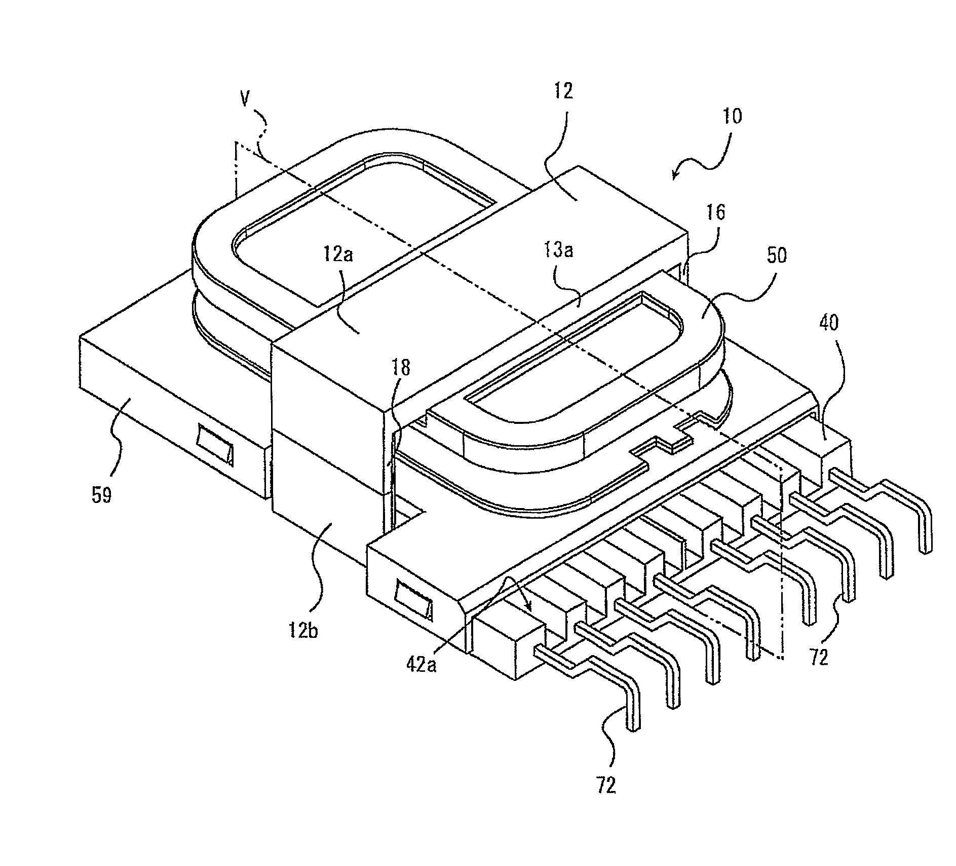
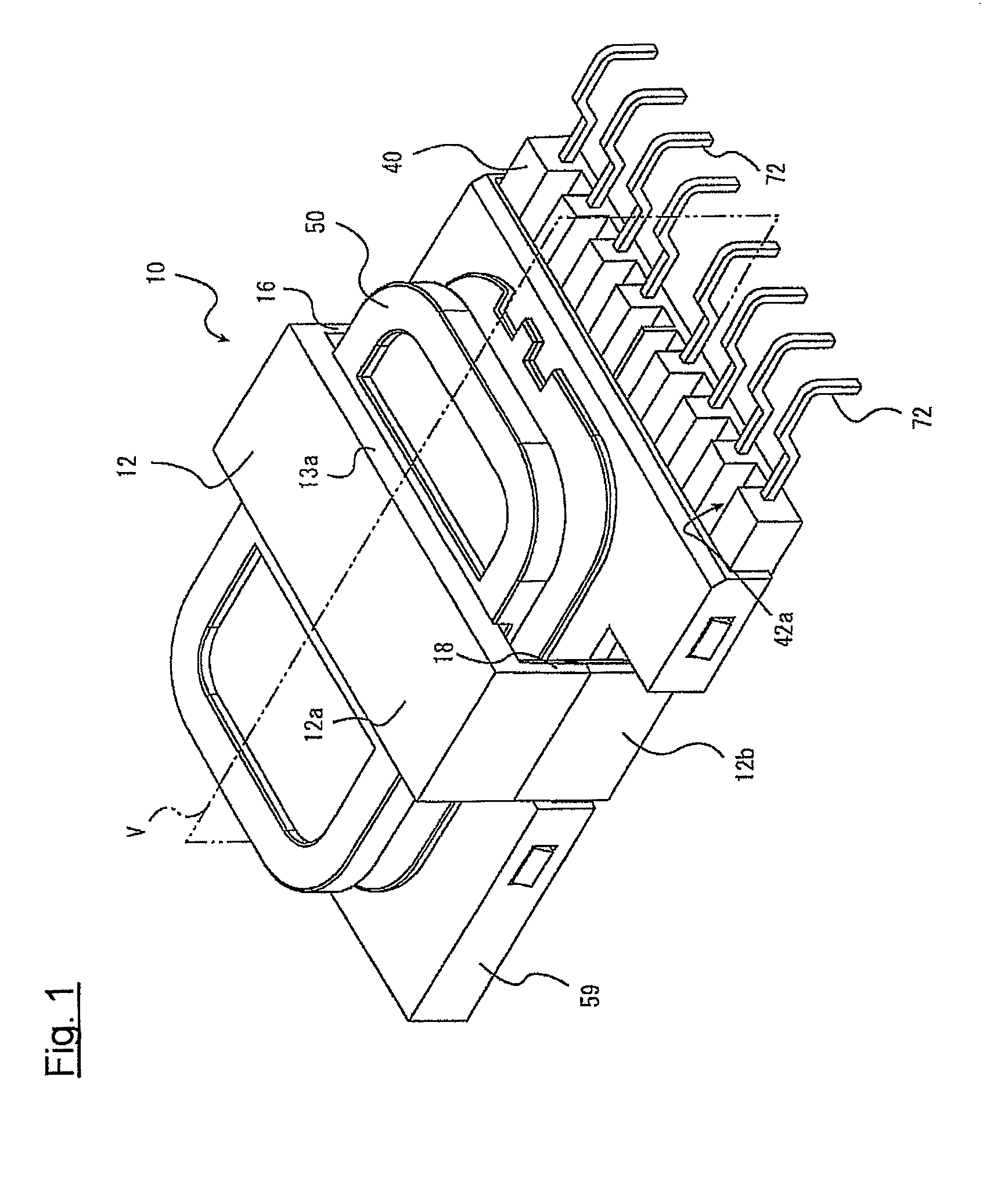
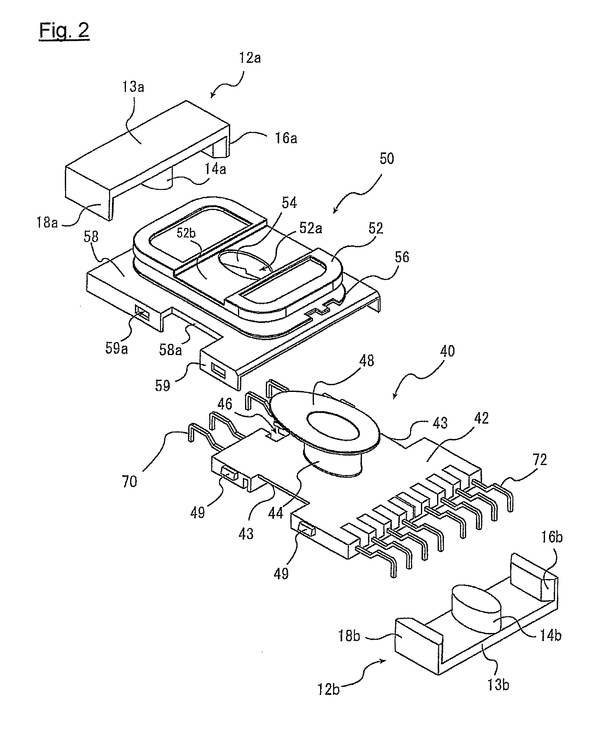
[0034]Case 50, shown in FIG. 2, determine a part of an outer shape of coil component 10, along with holding secondary coil 30 (See FIG. 4 and the like). Case 50 comprises upper surface part 52, second hollow part 54, under surface part 58 and side surface part 59, and etc. Upper surface part 52 is provided opposing to basal part 42 of bobbin 40, and is extended in parallel with the mounting surface. Upper surface part 52 forms through hole 52a, in order to insert middle leg 14 of core 12. Upper surface part 52 further forms installation groove part 52b, in order to install opposing part 13a of core 12.

[0035]The second hollow part 54 of case 50 stands out vertically downward from upper surface part 52. FIG. 5 is a cross sectional view of coil component 10, which is a cross section vertical to the mounting surface (See cross sectional line V of FIG. 1). Second hollow part 54 is formed to internally house primary coil 20 and middle leg 14. In other word, middle leg 14 and primary coil ...


PUM

PropertyMeasurementUnit
creeping distance D2aaaaaaaaaa
outer circumferenceaaaaaaaaaa
distanceaaaaaaaaaa

Abstract

The present invention provides a coil component which is possible to be thinner with less leakage flux toward upward and downward directions, and to sustain a good insulation. The coil component comprises a core including two opposing parts mutually opposing, two side legs mutually connect both ends of the two opposing parts, and a middle leg placed between the two side legs and mutually connect central parts of the two opposing parts, a primary coil, which goes around outer circumference of the middle leg, and a secondary coil, which goes around outer circumference of the primary coil, wherein; a distance between outer perimeter edge of the primary coil and inner perimeter edge of the secondary coil varies along circumferential direction.

Description

BACKGROUND OF THE INVENTION[0001]1. Field of the Invention[0002]The present invention relates to a coil component preferably used for a resonance transformer and the like.[0003]2. Description of the Related Art[0004]Coil components are used in various electrical products for various uses. For instance, when driving backlight of liquid glass display, inverter resonance transformer is used to obtain a high-voltage.[0005]Resonance transformer is requested to realize outward requirements such as low profile, in addition to electric characteristics such as occurrence of suitable leakage inductance. In order to meet such requirements, prior art proposes a coil component which is a horizontal-type wherein axial direction of core is parallel to the mounting surface, and which is a split structure wherein a primary coil and a secondary coil are separately arranged along the axial direction of core. Further, there is an advantage that the coil component of the split structure is relatively ea...

Claims


Application Information

Patent Timeline
Patent Type & Authority Patents(United States)
IPC IPC(8): H01F27/30
CPCH01F5/02H01F27/325H01F27/30H01F27/2823
Inventor MAEDA, HIROSHIKOBAYASHI, KATSUMIKITAJIMA, NOBUOHWANG, KIHO
Owner TDK CORPARATION
Why Eureka
Try Eureka