Spinning top

a spinning top and top technology, applied in the field of spinning tops, can solve the problems of not being able to stack another spinning top to the conventional spinning top, and achieve the effects of facilitating the gripping prolonging the spinning time of the spinning top, and reducing the number of spinning tops

Inactive Publication Date: 2014-10-28
SHYE CHI ENTERPRISE
View PDF24 Cites 1 Cited by
  • Summary
  • Abstract
  • Description
  • Claims
  • Application Information

AI Technical Summary

Benefits of technology

[0008]The advantage of this invention resides in that through the annular grip portion that extends outwardly and radially from the base portion, gripping of the spinning top can be facilitated, so that not only a greater throwing force can be imparted, but also the centrifugal force generated during spinning of the spinning top can be increased, thereby prolonging the spinning time of the spinning top. Further, through the presence of the central tapered groove, a second spinning top may be spun on the central tapered groove of a first spinning top. Hence, a plurality of spinning tops may be stacked on top of each other while spinning.

Problems solved by technology

Further, a top face of the main body 11 has a conical shape with a tip end facing upward, so that it is not possible to stack another spinning top to the conventional spinning top 1 while spinning.

Method used


Image

  • Spinning top
  • Spinning top
  • Spinning top

Examples


Embodiment Construction

[0022]Before the present invention is described in greater detail, it should be noted that the same reference numerals have been used to denote like elements throughout the specification.

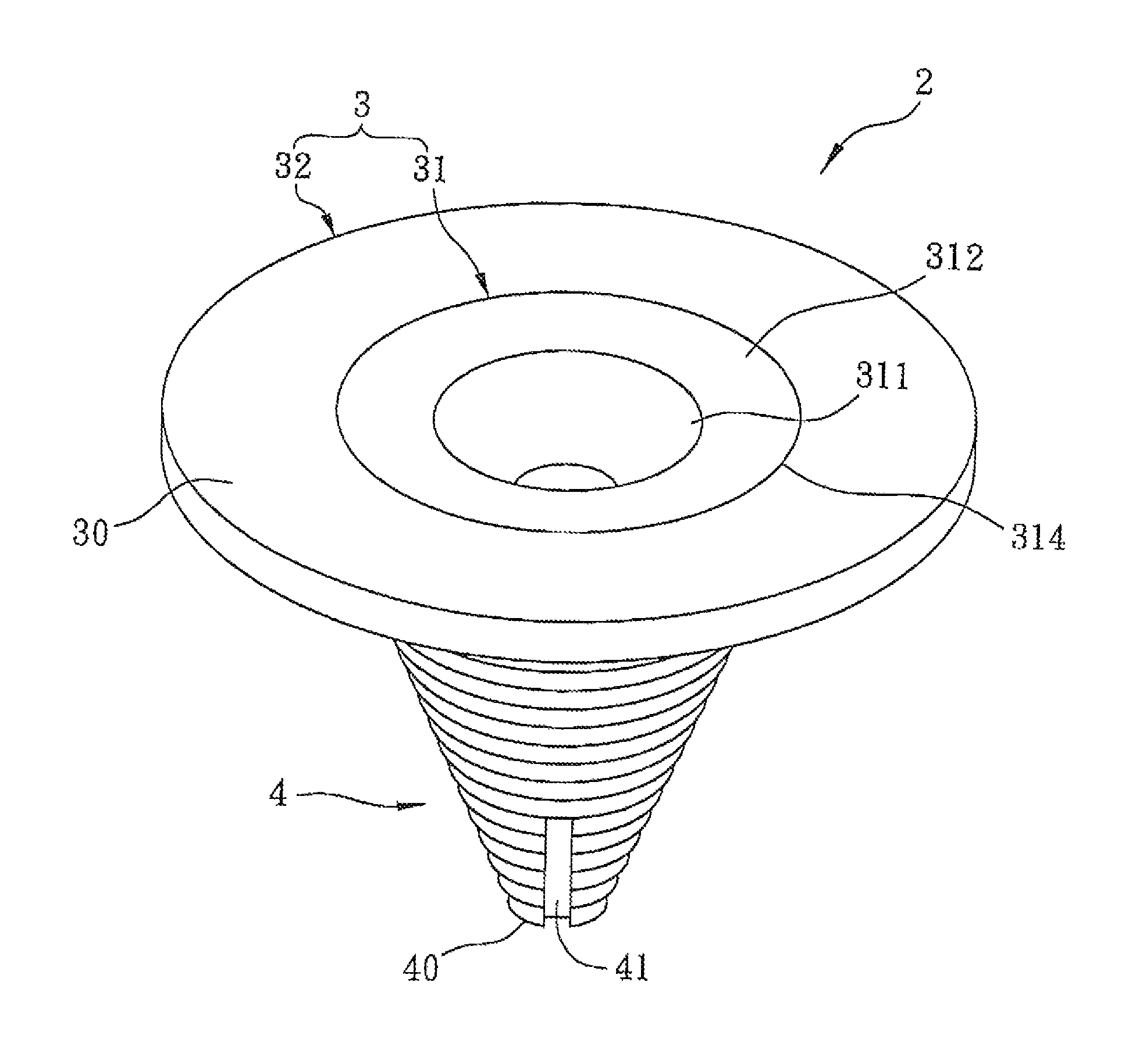
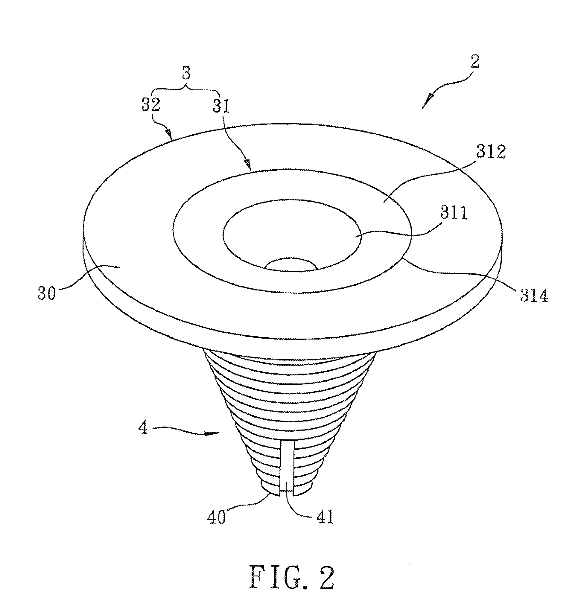
[0023]Referring to FIGS. 2 to 5, a spinning top 2 according to the first preferred embodiment of this invention is shown to comprise a plate body 3 and a main body 4.

[0024]The plate body 3 includes a base portion 31, an annular grip portion 32 extending outwardly and radially from an outer periphery of the base portion 31, and a top face 30 defined by top surfaces of the base portion 31 and the grip portion 32. The base portion 31 has a central tapered groove 311 tapering downwardly from the top face 30 of the plate body 3, and a slope area 312 that surrounds the central tapered groove 311 and that has an upper periphery 314 directly connected to the top face 30 of the plate body 3, and a lower periphery 316 connected directly to a top periphery 317 of the central tapered groove 311. The slope area ...


PUM


Abstract

A spinning top includes a main body tapering from a top end to a bottom end thereof and having a rotating tip end at the bottom end, and a plate body including a base portion connected to and covering the top end of the main body, an annular grip portion extending outwardly and radially from the base portion, and a top face defined by top surfaces of the base portion and the annular grip portion. The base portion has a central tapered groove tapering downwardly from the top face of the plate body. The rotating tip end has a diameter smaller than a smallest diameter of the central tapered groove.

Description

BACKGROUND OF THE INVENTION[0001]1. Field of the Invention[0002]This invention relates to a spinning top, and more particularly to a spinning top that can be spun for a prolonged period of time.[0003]2. Description of the Related Art[0004]Referring to FIG. 1, a conventional spinning top 1, as disclosed in Taiwanese Publication No. 200948447, includes a main body 11, and a shaft 12 projecting downward from the main body 11. In use, a cord 13 is wound around the main body 11, and is pulled at one end 131 thereof to spin the main body 11 and the shaft 12.[0005]As shown in FIG. 1, the main body 11 of the conventional spinning top 1 has a simple configuration that tapers downward, and has no structure that can increase centrifugal force, so that the spinning time of the top 1 cannot be prolonged. Further, a top face of the main body 11 has a conical shape with a tip end facing upward, so that it is not possible to stack another spinning top to the conventional spinning top 1 while spinni...

Claims


Application Information

Patent Timeline
Patent Type & Authority Patents(United States)
IPC IPC(8): A63H1/00
CPCA63H1/18A63H1/24A63H1/04
Inventor TSAI, CHAO-YANG
Owner SHYE CHI ENTERPRISE
Why Eureka
Try Eureka