Graft fixation device

a technology for fixing devices and knees, applied in the field of graft fixation devices, can solve problems such as excessive and/or uncontrolled motion about a particular joint, damage to connective soft tissue, and sometimes exceeding the limits of the demands placed on the kn

Active Publication Date: 2014-10-28
ARTHREX
View PDF16 Cites 73 Cited by
  • Summary
  • Abstract
  • Description
  • Claims
  • Application Information

AI Technical Summary

Benefits of technology

[0009]By way of example only, the device can be used to fix a graft to a support structure, such as a bone tunnel, by placing the sheath into the tunnel between strands of the graft and then inserting the member into the bore of the sheath body. This causes outwards radial displacement of the projections relative to the sheath body so that they contact and compress the graft against the tunnel wall creating strong, rigid fixation.
[0058]It is desirable that the graft is tensioned and cycled before fixation. Initially the sheath forming part of the device of the present invention may be inserted using an introducer or insertion tool so that the projections are aligned with the four strands of the graft. The sheath may then be fully inserted before the member is inserted into the sheath at which point the projections are displaced radially outwardly so as to contact and compress the graft strands against the tibial tunnel wall. Fixation of the graft may also be assisted by outward radial expansion of the sheath body upon insertion of the member into the sheath. This expansion is facilitated in part by the apertures defined by the sheath associated with the projections and in part by the flexible properties of the material from which the sheath is manufactured. Typically, the level of outward radial expansion of the sheath body may be up to around 1 mm, which equates to a total increase in cross sectional diameter of the sheath body of up to around 2 mm.

Problems solved by technology

Damage to connective soft tissue, for example ligaments and tendons, often results from excessive and / or uncontrolled motion about a particular joint, such as the knee or elbow.
The demands placed on the knee sometimes exceed its limits and if the ligament is stretched too tightly, it can tear or rupture.
This type of injury most commonly happens to athletes when quickly pivoting or changing direction.
In spite of surgical advances, the failure rate of ACL reconstruction is quoted to be in the range of 5 to 25%, with the main cause of graft failure being loss of graft fixation within the tibial bone tunnel.
A disadvantage of using such screws is the screw thread which provides the fixation within the bony tunnel.
The larger and sharper the thread the better the fixation, but conversely the greater the damage caused to the tendon and therefore the risk of failure.
Moreover, as ACL reconstruction is increasingly being performed on a more active older population with reduced bone quality, the ACL reconstruction failure rate is set to increase still further unless improved forms of fixation are developed.

Method used


Image

  • Graft fixation device
  • Graft fixation device
  • Graft fixation device

Examples


examples

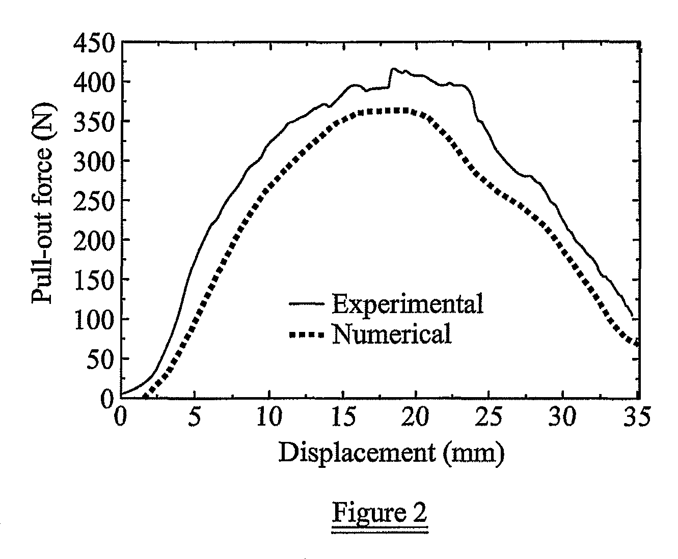
[0089]Experimental studies on animal models and computer simulations were carried out in the context of an ACL reconstruction. The experimental tests provided basic material data which was needed to understand the failure modes of ACL reconstruction, as well as to provide information needed for modeling and verification of the simulation. The computer modeling provided technical information which could not have been obtained as easily via pure experimental investigation, such as stress distributions, interfacial loading between the ligament graft, sheath / screw and bones, and first point of failure. The simulation also provided a means to allow various parameters to be tested so as to optimize the design of the fixation device of the present invention without requiring extensive experimental investigation. Experimental tests were then carried out to determine the performance of an nonoptimized prototype device according to the present invention for comparison to a commercially availa...


PUM


Abstract

A graft fixation device comprising a sheath having a body that defines an inner longitudinal bore and a member for insertion within the bore. The sheath includes at least two projections movably connected to the sheath body by a distal hinge. The distal hinge causes the projection to pivot inwardly as the sheath is placed in a bone tunnel, and to be displaceable radially outwardly of the sheath body upon insertion of the member within the bore.

Description

RELATED APPLICATIONS[0001]This is a continuation-in-part of International Patent Application No. PCT / GB2008 / 01800, filed on May 27, 2008, which in turn claims priority under 35 U.S.C. §119 to U.K. Application No. 07100233, filed May 25, 2007, the disclosures of which incorporated by reference in their entirety.BACKGROUND OF THE INVENTION[0002]The present invention relates to graft fixation devices comprising a sheath having a body that defines an inner longitudinal bore and a member for receipt within said bore. The device may be used to fix any form of graft, for example a soft tissue graft, such as a graft ligament or tendon, to a support structure, such as a joint with a preformed bone tunnel.[0003]Damage to connective soft tissue, for example ligaments and tendons, often results from excessive and / or uncontrolled motion about a particular joint, such as the knee or elbow. In severe cases, surgery can be required to restore the joint's function by replacement or reconstruction of...

Claims


Application Information

Patent Timeline
Patent Type & Authority Patents(United States)
IPC IPC(8): A61B17/88A61F2/08
CPCA61F2002/0858A61F2/0811A61F2002/0835
Inventor KOOGLE, JR., DAVID, C.
Owner ARTHREX
Why Eureka
Try Eureka