Fuel cell system

a fuel cell and battery technology, applied in the field of fuel cell systems, can solve the problems of hindering the operation of the fuel cell system, and achieve the effects of reducing the likelihood of operation failure, preventing undesirable drying of dry fuel cells, and prolonging the operation time of the fuel cell battery

Active Publication Date: 2014-10-28
TOYOTA JIDOSHA KK
View PDF23 Cites 0 Cited by
  • Summary
  • Abstract
  • Description
  • Claims
  • Application Information

AI Technical Summary

Benefits of technology

[0018]According to at least one of the above-described structures, the fuel cell system forcibly drives the fluid circulating device at least once every so many trips, which are one or more trips in which the fuel cell battery is operated. The fuel cell system might be provided with a fluid circulating device and the like which are normally operated only under certain conditions such as a low temperature, and are not driven unless they are exposed to these specific conditions. Thus, even if the fuel cell system is operated, the fluid circulating device may not necessarily be driven, increasing the likelihood that the fluid circulating device will become stuck due to extend non-use. By employing a configuration as described above, the fluid circulating device is forcibly driven at least once during each prescribed number of trips, thereby greatly reducing the likelihood of operational failure due to sticking of the circulating device.
[0019]By employing at least one of the above-described structures, the fuel cell system forcibly drives the fluid circulating device when the idle time of the fluid circulating device exceeds a predetermined amount of time. In this manner, the likelihood of, for example, a sealing surface of the forcible drive means such as an ON-OFF valve becoming stuck due to a long period of non-use can be greatly reduced.
[0020]In a fuel cell system employing the present invention, because the fluid circulating device is forcibly driven during steady operation of the fuel cell main body, treatment to inhibit sticking can be performed without extending the operation time of the fuel cell battery.
[0021]In a fuel cell system employing the present invention, when the fuel cell main body has a high temperature exceeding a predetermined temperature range, forced driving of the fluid circulating device is prohibited. When the fuel cell main body has a high temperature, for example, the saturated steam pressure of the oxidizing gas is high, and the fuel battery is in a dry state. By employing a configuration as described above, further undesirable drying of dry fuel cells can be prevented.
[0022]In a fuel cell system employing the present invention, when the impedance of the fuel cell battery exceeds a predetermined value, forced driving of the fluid circulating device is prohibited. When the fuel cell battery has a high impedance, the fuel cells are in a dry state. By employing a configuration as described above, further undesirable drying of dry fuel cells can be prevented.
[0023]In a fuel cell system employing the present invention, the fluid circulating device is forcibly driven when it is judged that background exceeds a predetermined value, as determined based on a measured value related to the background noise. Thus, noise when the fluid circulating device is forcibly driven can be made unnoticeable.

Problems solved by technology

If such a fluid circulating device does not operate, the operation of the fuel cell system may be hindered; various measures have been employed to deal with failure of such devices.

Method used


Image

  • Fuel cell system
  • Fuel cell system
  • Fuel cell system

Examples


Embodiment Construction

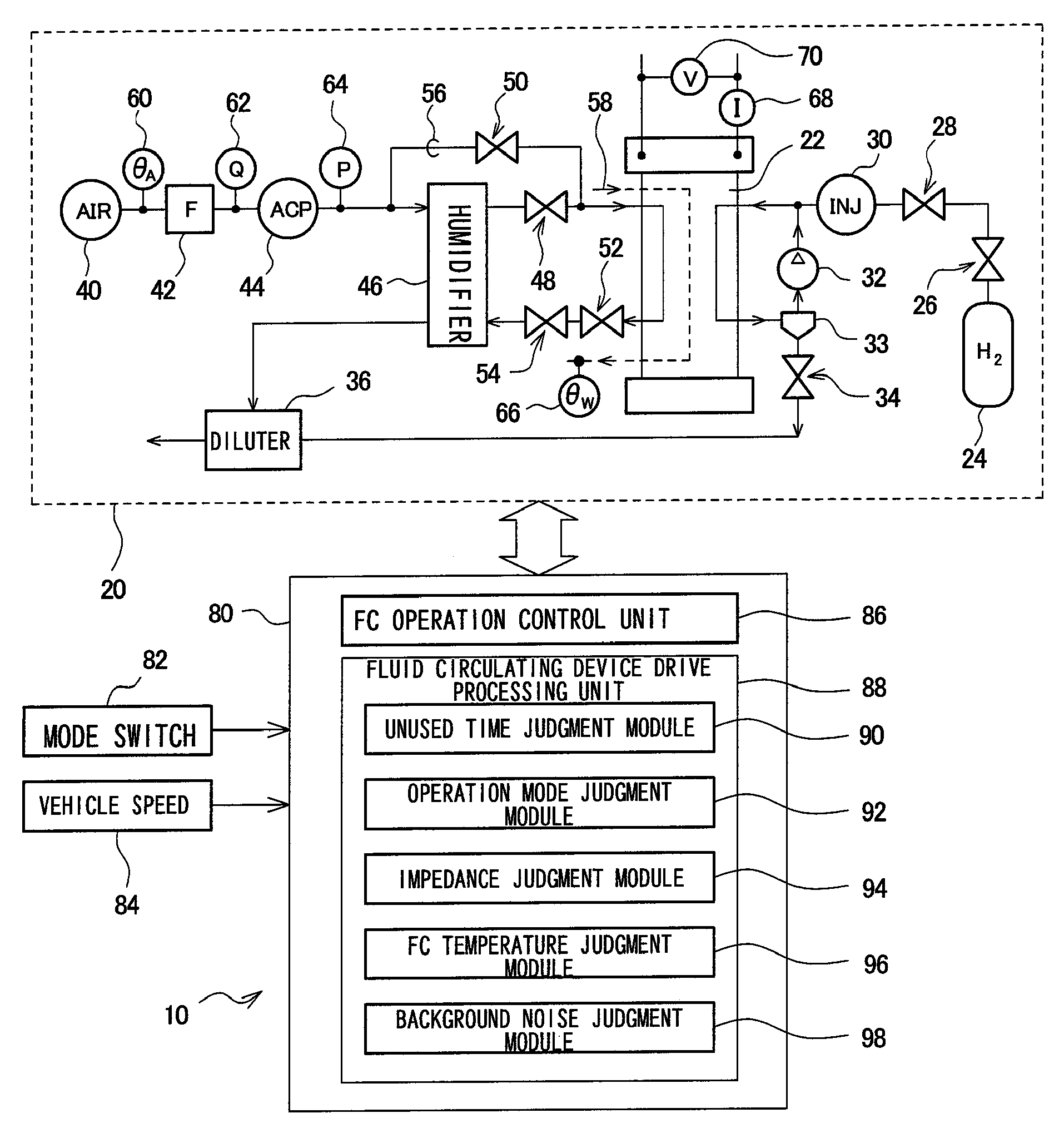
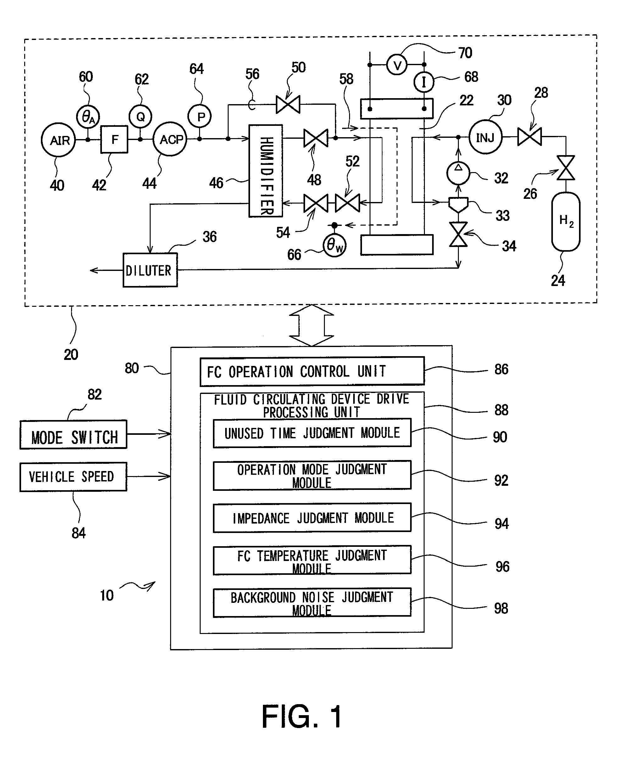
[0030]An embodiment of the present invention is described in detail below with reference to the drawings. In the illustrated example, a fuel cell system to be mounted on a vehicle is described below, but this system may be a fuel cell system which is not operated continuously but only on demand, or may be a fuel cell system intended for uses other than in vehicles. Although a fuel cell system having a fuel cell main body of a solid polymer electrolyte membrane type using hydrogen for the fuel gas and the atmosphere for the oxidizing gas, is described below, the present invention may be applied to fuel cell systems having other types of fuel cell main body using other types of gas and other types of electrolyte membranes, as long as it is provided with a fluid circulating device which is disposed in a fluid passage connected to the fuel cell main body. A humidifier bypass valve drive device which is disposed as a fluid circulating device in a humidifier bypass passage for bypassing t...


PUM

PropertyMeasurementUnit
output voltageaaaaaaaaaa
speedaaaaaaaaaa
temperatureaaaaaaaaaa

Abstract

In a fuel cell system, it is possible to suppress fixation of a fluid circulating device arranged in a fluid passage connected to a fuel cell main body. The fuel cell system is provided with a fuel cell stack, a system main body having respective elements for supplying a fuel gas and respective elements for supplying an oxidizing gas, and a control device. The control device includes a fluid circulating device drive processing unit having a function to forcibly drive the fluid circulating device after determining, based on a judgment related to one or more of a non-use time, an operation state of the system main body, a membrane impedance state of a fuel cell, a temperature of the fuel cell stack, and a background noise, whether or not forced driving to suppress sticking of the fluid circulating device is preferable at that time.

Description

[0001]This is a 371 national phase application of PCT / JP2008 / 067182 filed 24 Sep. 2008, claiming priority to Japanese Patent Application No. JP 2007-257735 filed 1 Oct. 2007, the contents of which are incorporated herein by reference.BACKGROUND[0002]1. Technical Field[0003]The present invention relates to a fuel cell system, and more particularly to a fuel cell system including a fluid circulating device which is disposed in a fluid passage connected to a fuel cell main body.[0004]2. Related Art[0005]An advantage of installing batteries comprised of fuel cells on in vehicles is that their impact on the environment is relatively small. Fuel cells generate required electric power by, for example, reacting a fuel gas such as hydrogen supplied to an anode side of a fuel cell with an oxidizing gas such as air supplied to a cathode side, causing a reaction through an electrolyte membrane. Because heat is generated as a result of such a reaction, a coolant such as cooling water is circulat...

Claims


Application Information

Patent Timeline
Patent Type & Authority Patents(United States)
IPC IPC(8): H01M8/04
CPCY02T90/32H01M2250/20H01M8/04634H01M8/04783H01M8/0432Y02E60/50H01M8/04313H01M8/04753Y02T90/40
Inventor KAJIWARA, SHIGETOBONO, TETSUYA
Owner TOYOTA JIDOSHA KK
Why Eureka
Try Eureka