One camera stereo system

a stereo system and camera technology, applied in the field of single camera, can solve the problem of a large error in estimating side angles, and achieve the effect of accurate three-dimensional information

Active Publication Date: 2014-10-28
ACUSHNET CO
View PDF203 Cites 64 Cited by
  • Summary
  • Abstract
  • Description
  • Claims
  • Application Information

AI Technical Summary

Benefits of technology

[0011]In many golf applications, camera systems are often used to gather three dimensional coordinate information by marking an object in space and imaging at least two pictures of the object from two viewpoints with a camera, such as a CCD camera. Previous one camera methods often required a scale marking to be placed on the object being measured to measure three dimensional information, such as depth. The present invention allows one camera to create more accurate three dimensional information of the position and orientation of an object without scale marking used in previous methods.
[0012]One camera systems often require the markers placed on a ball to be placed at precisely known points on the surface of the ball. As shown in U.S. Pat. No. 5,471,383, which is incorporated herein by reference, a one camera system with precisely located markers often results in a much larger error when estimating side angle than a two camera system that does not require precisely located markers. The present invention allows the improved accuracy of a two camera system to be realized by one camera, beam splitter, and a mirror.

Problems solved by technology

As shown in U.S. Pat. No. 5,471,383, which is incorporated herein by reference, a one camera system with precisely located markers often results in a much larger error when estimating side angle than a two camera system that does not require precisely located markers.

Method used


Image

  • One camera stereo system
  • One camera stereo system
  • One camera stereo system

Examples


Embodiment Construction

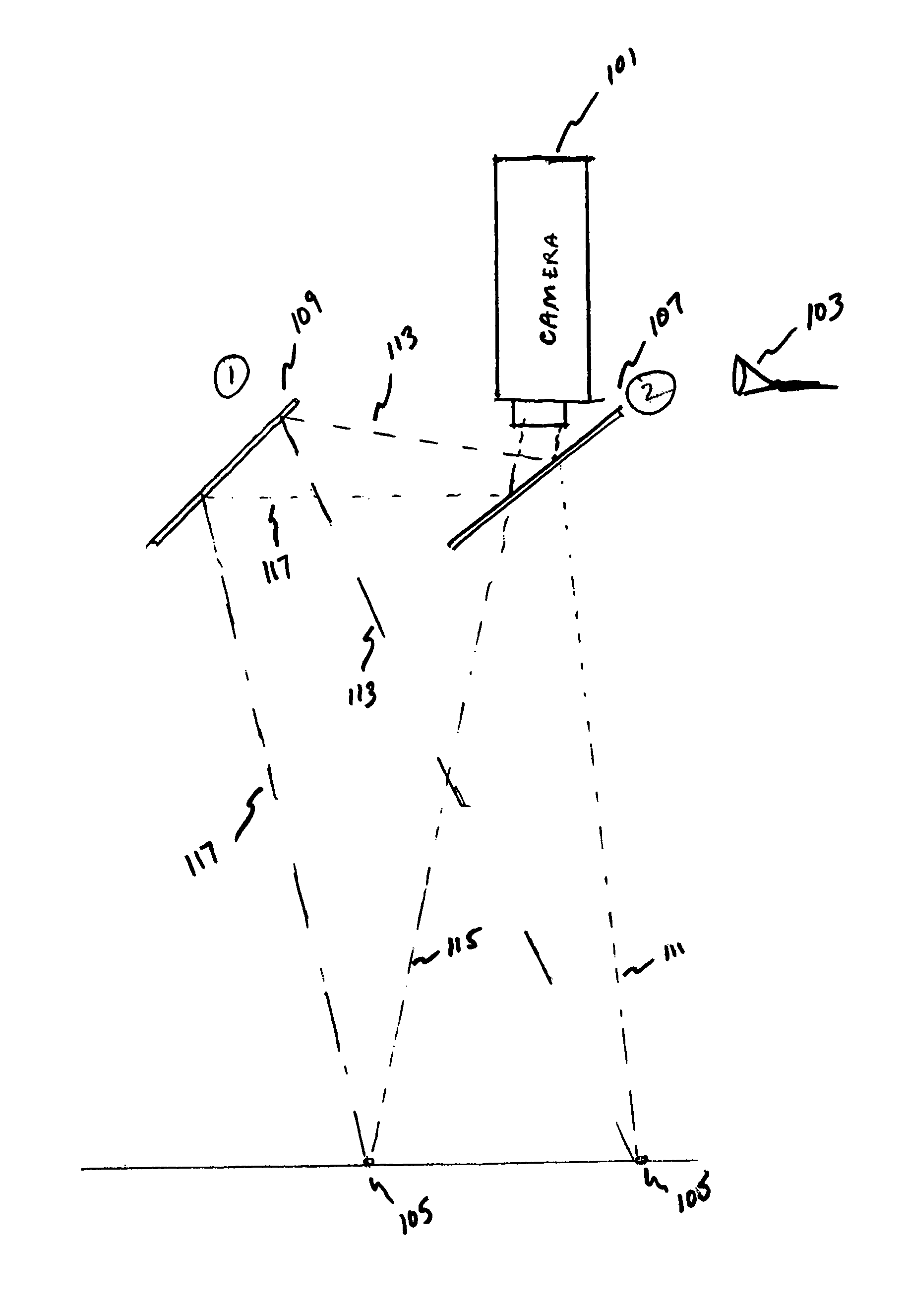
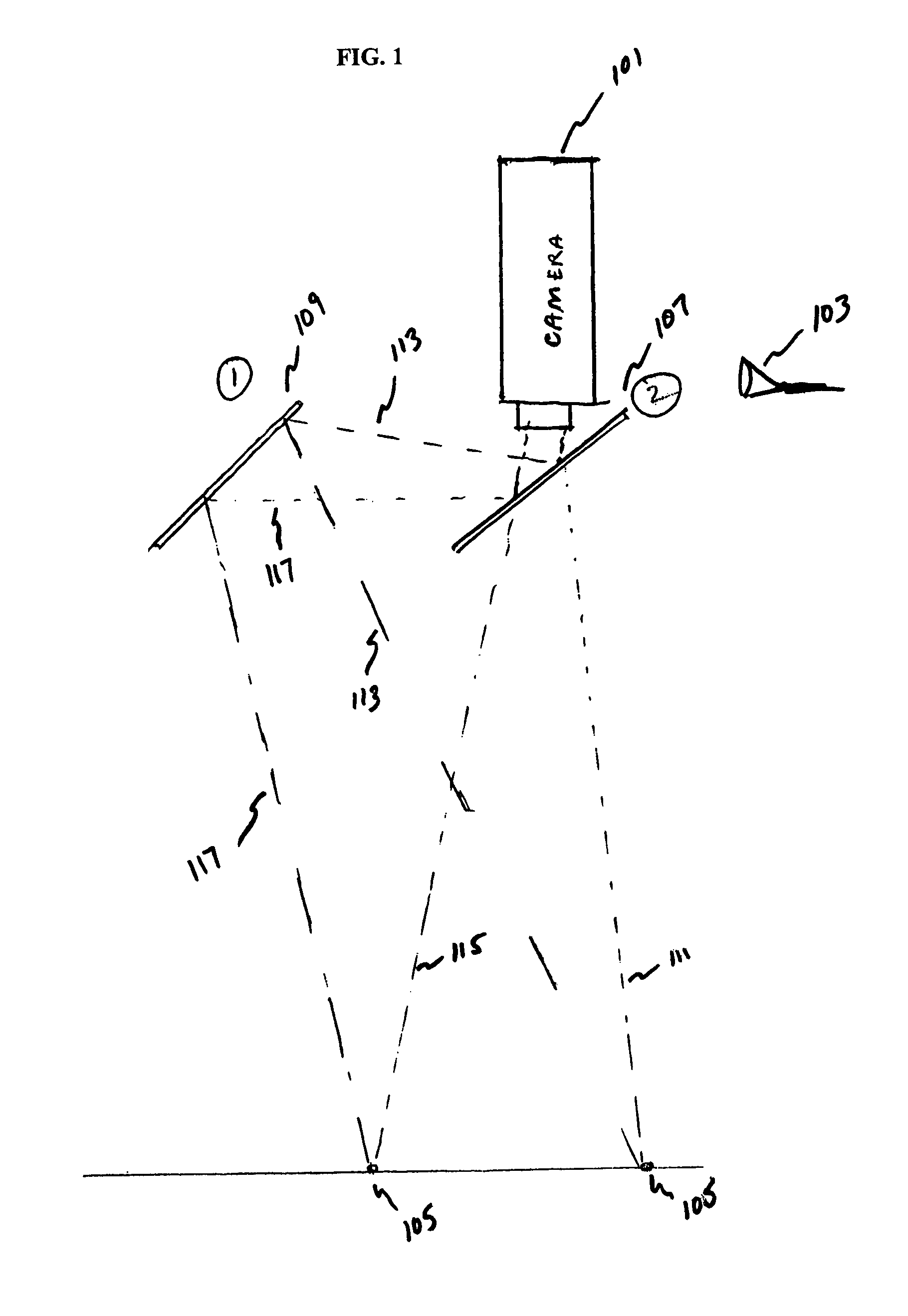
[0029]In many golf applications, camera systems are often used to gather three dimensional coordinate information by marking an object in space and imaging at least two pictures of the object from two viewpoints with a camera, such as a CCD camera. Previous one camera methods often required a scale marking to be placed on the object being measured to measure three dimensional information, such as depth. The present invention allows one camera to create more accurate three dimensional information of the position and orientation of an object without scale marking used in previous methods.

[0030]One camera systems often require the markers placed on a ball to be placed at precisely known points on the surface of the ball. As shown in U.S. Pat. No. 5,471,383, which is incorporated herein by reference, a one camera system with precisely located markers often results in a much larger error when estimating side angle than a two camera system that does not require precisely located markers. ...


PUM


Abstract

A one camera system that measures golf club and golf ball kinematics is disclosed. Preferably, a plurality of retroreflective or fluorescent markers are placed on the surface of a golf ball. Using a single strobe lamps, images of a golf ball at two points in motion are acquired. The output of each of the strobe lamps is preferably filtered to pass predetermined colors of light. The input to each of the cameras is also preferably filtered. The output from the strobe lamp passes through at least one of a beam splitting mirror and reflective front surface mirror. Based on the filtered light outputs generated by the strobe lamp and the filtered camera input, at least two images of the golf ball, taken from two different angles, may be acquired. The acquired images may be used to analyze the kinematics of the golf ball.

Description

FIELD OF THE INVENTION[0001]The present invention relates to a single camera that can capture two views of a desired scene. More specifically, the present invention uses a beam splitting mirror and a front surface mirror arranged to present a second viewing angle of the scene being observed.BACKGROUND OF THE INVENTION[0002]Golf equipment manufacturers currently spend a large amount of time and money on research and development related to better golf clubs and golf balls. Their innovation has led to the development of golf clubs and balls with a wide range of performance characteristics to account for many different types of golfers. Golf clubs may have varying shaft lengths or stiffness. Golf clubs may be manipulated to have different head characteristics, such as loft or lie angle. They may even be manufactured with various combinations of materials in order to attain a specific coefficient of restitution (COR).[0003]Similarly, golf balls have been developed and researched in a sim...

Claims


Application Information

Patent Timeline
Patent Type & Authority Patents(United States)
IPC IPC(8): H04N13/00A63B69/38H04N13/02A63B69/00A63B69/36A63B24/00H04N7/18H04N5/225
CPCA63B2024/0034A63B69/0002A63B69/3658A63B24/0021A63B2243/007H04N13/0217A63B69/3614A63B69/38H04N13/218
Inventor GOBUSH, WILLIAM
Owner ACUSHNET CO
Why Eureka
Try Eureka