Unlock instant, AI-driven research and patent intelligence for your innovation.

Display control method and device for finder device

a technology of display control and finder device, which is applied in the direction of exposure control, television systems, instruments, etc., can solve the problems of camera shake, difficult to watch the liquid crystal display panel itself, and inability to confirm an image of a subj

Active Publication Date: 2014-10-28
FUJIFILM CORP
View PDF43 Cites 6 Cited by
  • Summary
  • Abstract
  • Description
  • Claims
  • Application Information

AI Technical Summary

Benefits of technology

This solution allows photographers to easily recognize images by gradually adjusting the brightness of the viewfinder, reducing the risk of dazzle and improving visual recognition during transitions between optical and electronic viewfinder modes.

Problems solved by technology

When compositional arrangement of a subject or the like is to be confirmed on the liquid crystal display panel provided in the back of the camera, it is difficult to watch the liquid crystal display panel itself if ambient light in the surroundings is too bright.
When the liquid crystal display panel in the back of the camera is used as a substitute for a finder, it is impossible to confirm an image of a subject unless the camera is kept away from a face (eye) to watch the subject.
However, when a photographer takes up such a posture to take a photograph, a camera shake occurs.
However, when the photographer views the image with such brightness in the finder, the photographer may be dazzled to make it difficult to visually recognize the image because the pupil of the photographer's eye cannot change quickly enough in accordance with the brightness of ambient light in the surroundings before viewing.
There is another problem that detailed portions of the compositional arrangement of the subject cannot be confirmed.
Moreover, because the through image is displayed, it takes time for image processing.
There is a further problem that a little time lag occurs compared with the actual state of the subject.
Accordingly, when the optical image of the subject is switched to an image in the electronic view finder or inversely the image in the electronic view finder is switched to that in the optical view finder or when the two are displayed so as to be superposed on each other, there is a possibility that the pupil of the photographer's eye cannot change quickly enough so that the photographer may be dazzled to make it difficult to visually recognize the image.

Method used


Image

  • Display control method and device for finder device
  • Display control method and device for finder device
  • Display control method and device for finder device

Examples


third embodiment

[0076]FIG. 11 is a view for explaining the invention. In a digital camera, when an image is taken and then image processing thereof is completed, the taken image is displayed on the LCD 40 or the EVF display device 61 in FIG. 2. This is called preview display. For example, the taken image is displayed for about 2 seconds as shown in FIG. 11. The time is not limited to 2 seconds. For example, the taken image may be displayed till next pushing-down of the shutter button.

[0077]When this preview display is performed by the finder device 15, there is a possibility that a photographer viewing the finder will be dazzled when the photographer views the preview display with 2000 Lx suddenly. Therefore, as shown in a lower half of FIG. 11, when preview display is performed on the EVF display device 61, brightness is increased stepwise gradually so that preview display with 2000 Lx is performed for 2 seconds finally. In this manner, preview display easy to see can be performed.

[0078]Incidental...

fourth embodiment

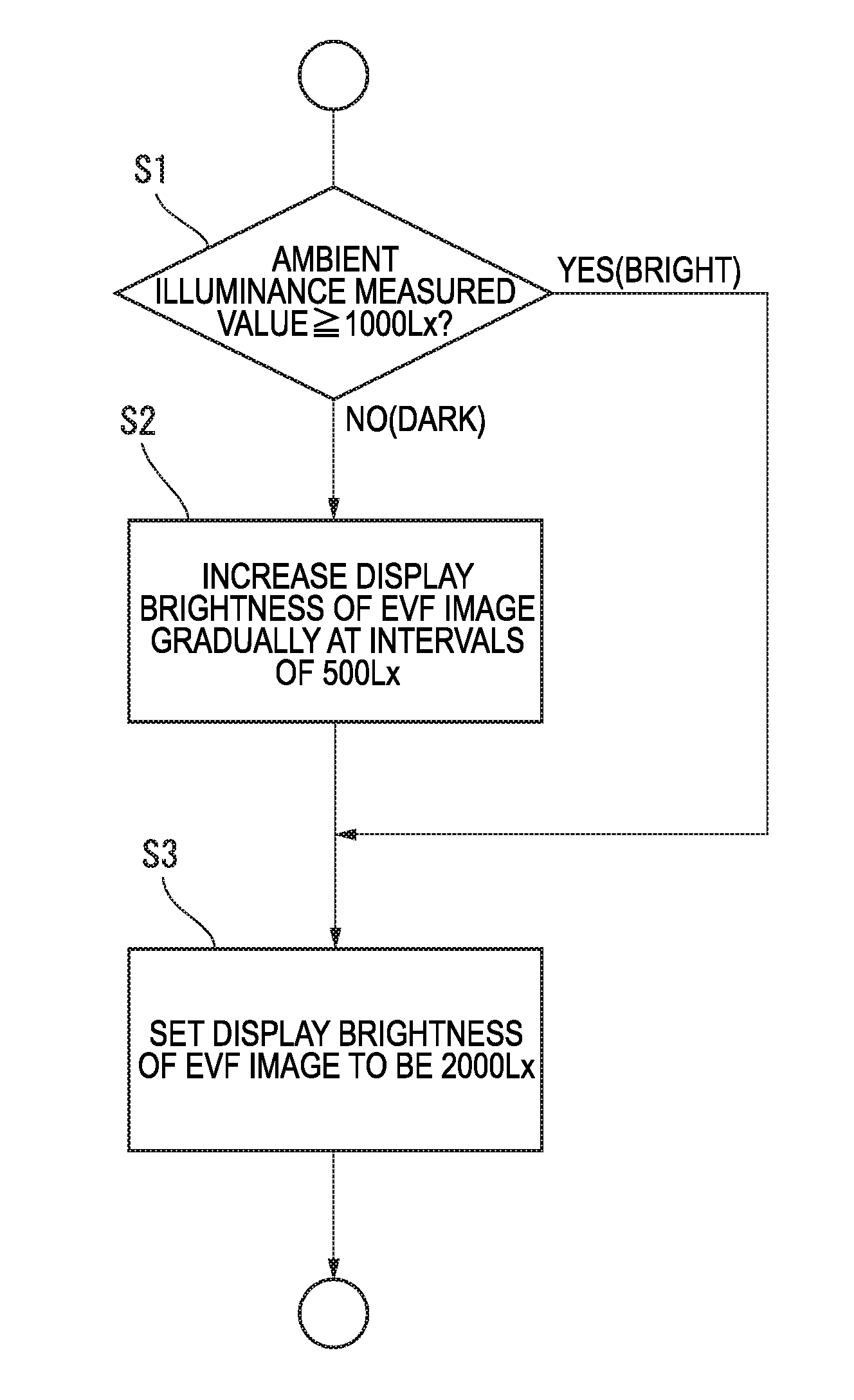
[0079]FIG. 12 is a flow chart showing a processing procedure in a brightness display control method according to the invention. In a single lens reflex digital camera, an optical image of a subject via an imaging lens is displayed in a finder. An EVF image can be displayed in the finder in the same manner as in the aforementioned embodiments.

[0080]The finder device 15 is equipped with an eye sensor which detects the photographer's viewing the finder to perform the following display control.

[0081]First, the camera waits for the eye sensor's detecting the photographer's eye (step S21). When the photographer's eye is detected, the flow of processing goes to next step S22. In the step S22, determination is made as to whether ambient illuminance is at least required brightness such as 1000 Lx or not. When determination is made that the camera is under a dark environment lower than 1000 Lx (determination results in No), the flow of processing goes to next step S23.

[0082]In the step S23, t...


PUM


Abstract

There are provided: a half mirror provided in a finder device and transmitting an incident light image from a subject side and projecting the incident light image onto a photographer side finder view window side; a display panel provided in a position facing the half mirror in the finder device and displaying a taken image of the subject taken by an imaging device with given brightness so that the displayed taken image (EVF image) is reflected by the half mirror so as to be projected onto the photographer side finder view window side; and a display control portion changing brightness of the display image (EVF image) displayed on the display panel so that the brightness of the display image (EVF image) increases gradually to given brightness or the brightness of the display image (EVF image) further increases gradually from the given brightness.

Description

CROSS REFERENCE TO RELATED APPLICATIONS[0001]This application is the Continuation of PCT / JP2011 / 061102 filed on May 13, 2011, which claims priority under 35 U.S.C 119(a) to Patent Application No. 2010-210226 filed in Japan on Sep. 17, 2010, all of which are hereby expressly incorporated by reference into the present application.TECHNICAL FIELD[0002]The present invention relates to a display control method and device for finder device mounted in an imaging apparatus such as a digital camera. Particularly, it relates to a display control method and device in which easiness in visual recognition of an image confirmed in a finder is improved.BACKGROUND ART[0003]Solid-state imaging devices are mounted in digital cameras. Therefore, there are lots of such cameras that a through image (live view image) of a subject outputted from a solid-state imaging device is displayed on a liquid crystal display panel or the like provided in the back of the camera or the like so that the liquid crystal ...

Claims


Application Information

Patent Timeline
Patent Type & Authority Patents(United States)
IPC IPC(8): H04N5/222H04N5/232G03B17/20G03B13/10G03B13/04G03B7/099G03B13/02
CPCG03B17/20H04N5/23293G03B13/04
Inventor JOGETSU, TADASHI
Owner FUJIFILM CORP