Front load refuse container and lift pocket assembly

a front load, refuse container technology, applied in the field of refuse hauling, can solve the problems of potential safety hazards, high cost and time consumption of containers, and significant amount of cutting and welding during fabrication of front load refuse containers, so as to improve the aesthetics of containers and reduce the number of visible weld seams.

Active Publication Date: 2014-11-04
HANKEY J DANIEL
View PDF12 Cites 1 Cited by
  • Summary
  • Abstract
  • Description
  • Claims
  • Application Information

AI Technical Summary

Benefits of technology

[0022]10. improve the aesthetics the container by providing rounded corners and fewer visible weld seams.

Problems solved by technology

Front load refuse containers (also called bins, cans, or dumpsters) require a significant amount of cutting and welding during their fabrication.
The end result of the prior art designs and fabrication methods is a container that is costly and time consuming to produce, not visually appealing because of the welded corners, and a potential safety hazard during fabrication and use because of the sharp corners and edges.
Further, the lift pockets, which take a beating from refuse truck forks, can fail at the weld seams.
Additionally, although not designed to provide a standing surface, the lift pockets invite standing on because either gussets are not used or, more typically, the gussets' flat surfaces are arranged at a very shallow angle relative to the end wall.
These objects fall off the pocket or rail as the container is being lifted by a refuse truck, damaging the truck or, worse, injuring its driver.

Method used


Image

  • Front load refuse container and lift pocket assembly
  • Front load refuse container and lift pocket assembly
  • Front load refuse container and lift pocket assembly

Examples


Embodiment Construction

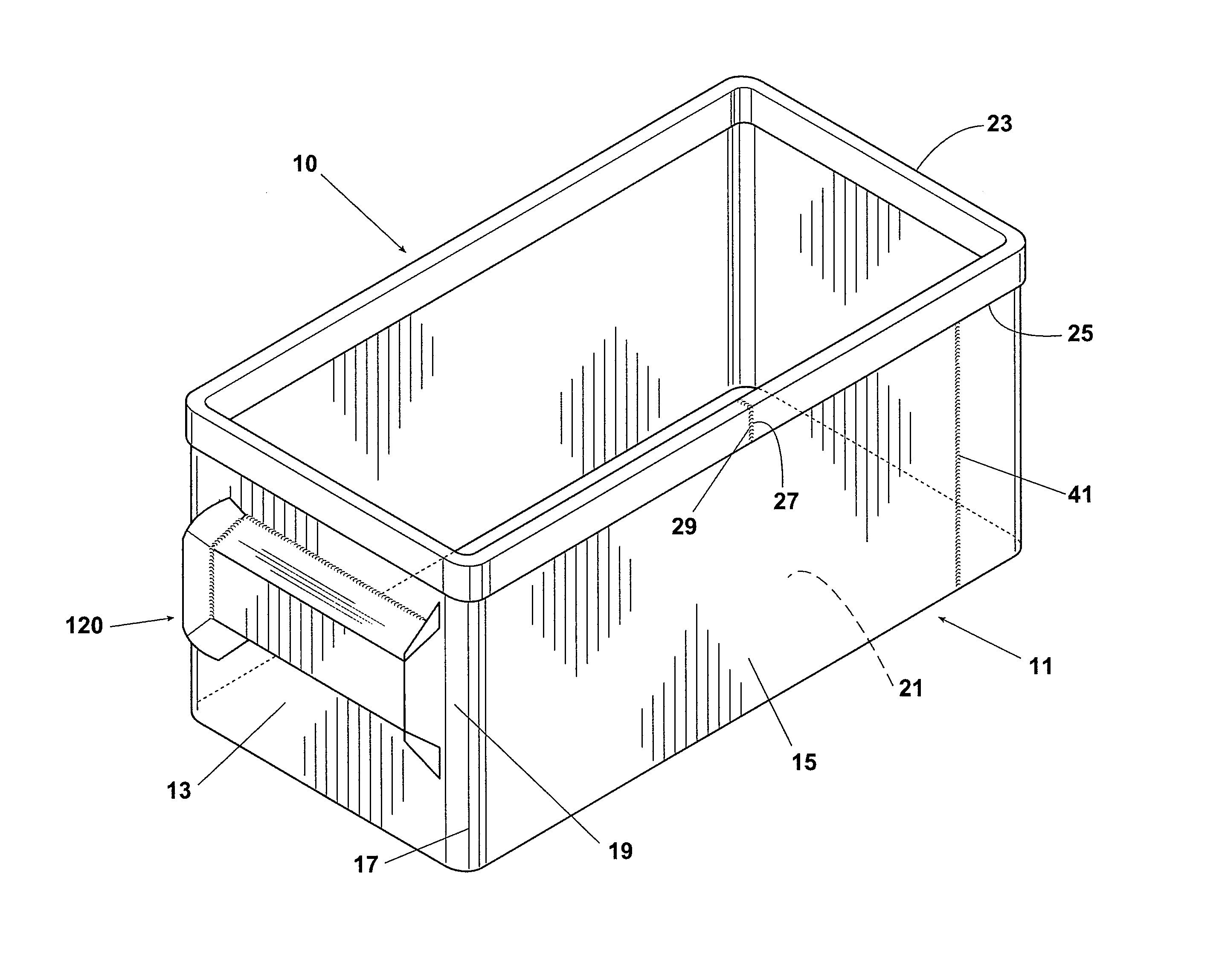
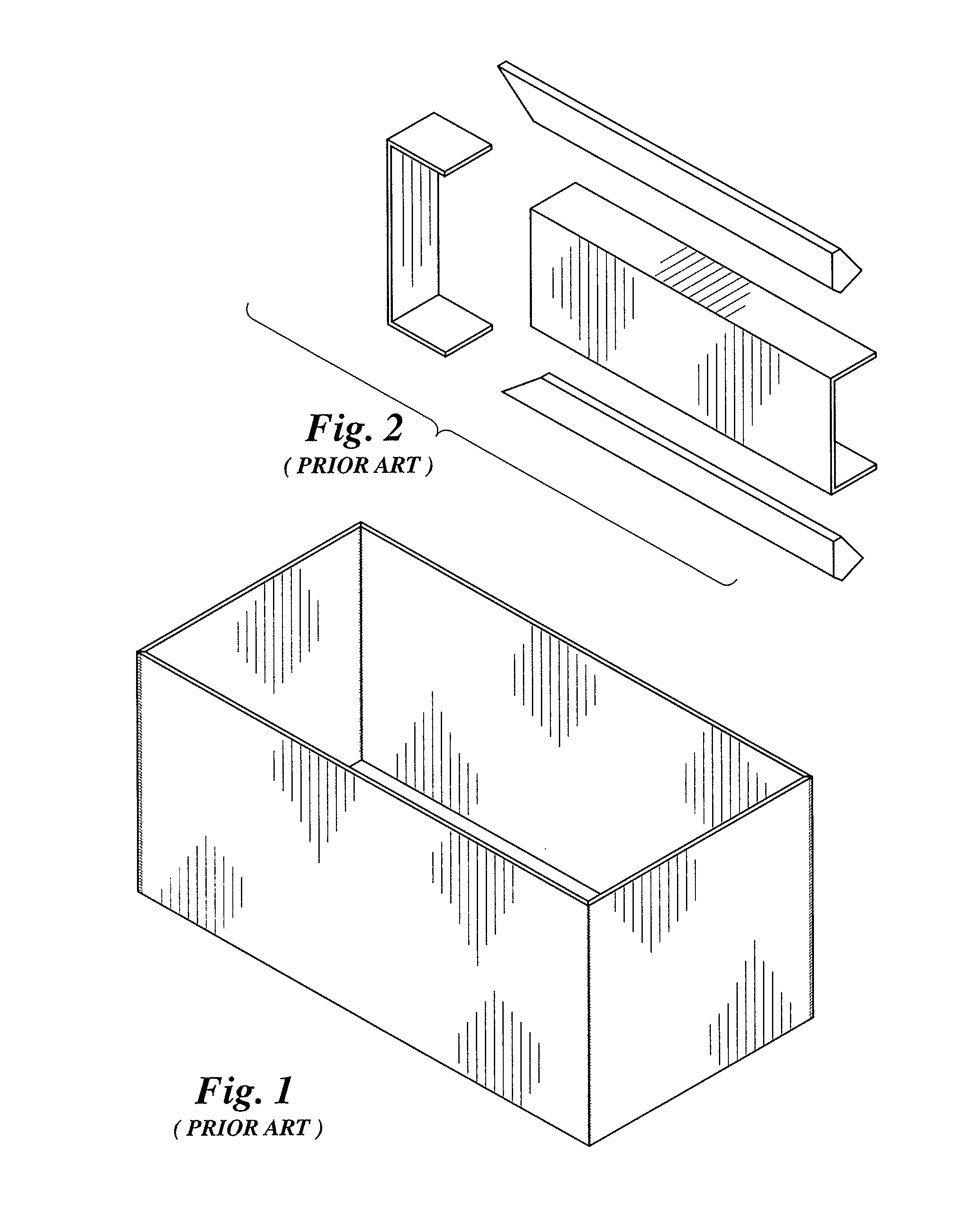
[0041]Referring to the drawings, and first to FIG. 4, a front load refuse container 10 made according to this invention has a container body 11 made up of two opposing end walls 13 and two opposing side walls 15 that, instead of being four individually cut-to-size and welded pieces (see FIG. 1), are integrally formed from a single steel sheet 30. Single sheet 30 is of a type and gauge typically used in fabricating refuse containers and is preferably cut to a desired dimension using a plasma cutter. The height and length of the cut sheet 30 is such that, once fabricated into container body 11, the container body 11 provides the volume or refuse capacity desired for container 10 (e.g. 2 cubic yards, 10 cubic yards).

[0042]Because sheet 30 can be cut-to-size within a 1 / 16 to 1 / 32-inch tolerance, using a single sheet 30 to form container body 11 significantly reduces the overall tolerance relative to that experienced with prior art container bodies, with their four individually cut-to-si...


PUM


Abstract

A front load refuse container made according to this invention has its four walls integrally formed out of a single piece of sheet metal. To form the walls, the single sheet is welded along a single vertical seam to form a circular-shaped ring. The circular-shaped ring is subjected to a swaging process that produces a rectangular-shaped ring with rounded corners.

Description

BACKGROUND OF THE INVENTION[0001]This invention generally relates to refuse hauling and, more particularly, to front load refuse containers sized in the range of 2 to 10 cubic yards and methods of their manufacture.[0002]Front load refuse containers (also called bins, cans, or dumpsters) require a significant amount of cutting and welding during their fabrication. The sheets, which make up the opposing side- and end-walls and floor, must be cut-to-size, transported to a welding operation, mated along the edges, and welded together. The structural tubing, which makes up the top rail and provides added rigidity and structural support to the wells, must also be cut-to-size, transported to a welding operation, fitted to the walls and to an adjacent rail, and welded to the walls and to each other. The sheets that make of the lift pockets which receive the forks of a refuse truck and typically include a U-shaped channel portion and gusset portions, must also be cut-to-size, transported to...

Claims


Application Information

Patent Timeline
Patent Type & Authority Patents(United States)
IPC IPC(8): B65D1/24
CPCB65F1/122B65F1/02B65F2250/11B65F1/1452
Inventor HANKEY, J., DANIEL
Owner HANKEY J DANIEL
Why Eureka
Try Eureka