Mobile crusher

a mobile crusher and crusher body technology, applied in the direction of wet separation, solid separation, mowers, etc., can solve the problems of heavy or cost-intensive, short range between material pickup and material discharge, complicated design, etc., and achieve the effect of simplifying the overall system

Inactive Publication Date: 2014-11-04
TAKRAF
View PDF10 Cites 6 Cited by
  • Summary
  • Abstract
  • Description
  • Claims
  • Application Information

AI Technical Summary

Benefits of technology

[0014]According to the invention, a mobile crusher is provided comprising four-caterpillar chassis, a supporting frame, a receiving hopper, an apron conveyor, a crusher / sizer and an intermediate conveyor. The supporting frame of mobile crusher comprises a framework with two side panels as well as lower and upper cross-ties. Under the feed side for the material to be crushed, the supporting frame is provided with a cross-box, at which the two rear longitudinal chassis are mounted via a long caterpillar axle or two short caterpillar axles on the outside. The rear longitudinal caterpillars are not controlled and have no drives, they are equipped with four-wheel rockers and two-wheel rockers for the uniform distribution of loads on the wheels. Under the loading side, the supporting frame is supported on the front two-caterpillar chassis by means of a ball and socket joint. The front caterpillars are connected to one another by means of a triangular crossbeam, to which one caterpillar is rigidly connected and the other caterpillar is movably connected via an axle. The front caterpillars can be controlled like a two-caterpillar chassis and they can be rotated into any direction in relation to the support structure, they have powerful drives and are equipped with four-wheel rockers and two-wheel rockers for the uniform distribution of loads on the wheels. The distance between the front and rear sets of caterpillars is deliberately selected to be great to keep the load change on the caterpillars as small as possible because of the large hopper load. All four chassis of the crusher unit are dimensioned so that displacement with full load capacity can take place in the hopper, on the apron conveyor and on the intermediate conveyor. The receiving hopper and the apron conveyor are integrated firmly in the supporting frame. The sizer (crusher / sizer) is placed on the supporting frame and can be easily driven out of the working position into a service position in the direction of the discharge side. The intermediate conveyor, between crusher / sizer and the material discharge is integrated firmly in the supporting frame. The containers for the electrical systems as well as the grease lubricating system of the crusher are arranged easily accessibly next to the lower panel of the supporting frame.
[0030]The combination of a mobile crusher unit without pivoting belt and a mobile bridge is particularly advantageous. Herein, the number of conveyor belts is minimized, which keeps the operating costs low. Moreover, the mobile bridge optimally bridges over the operating ramps needed for the up and down steps.

Problems solved by technology

The solutions described above have either a very short overall length, which keeps the range between material pickup and material discharge short, or they have a complicated design, are heavy or cost-intensive.

Method used


Image

  • Mobile crusher
  • Mobile crusher
  • Mobile crusher

Examples


Embodiment Construction

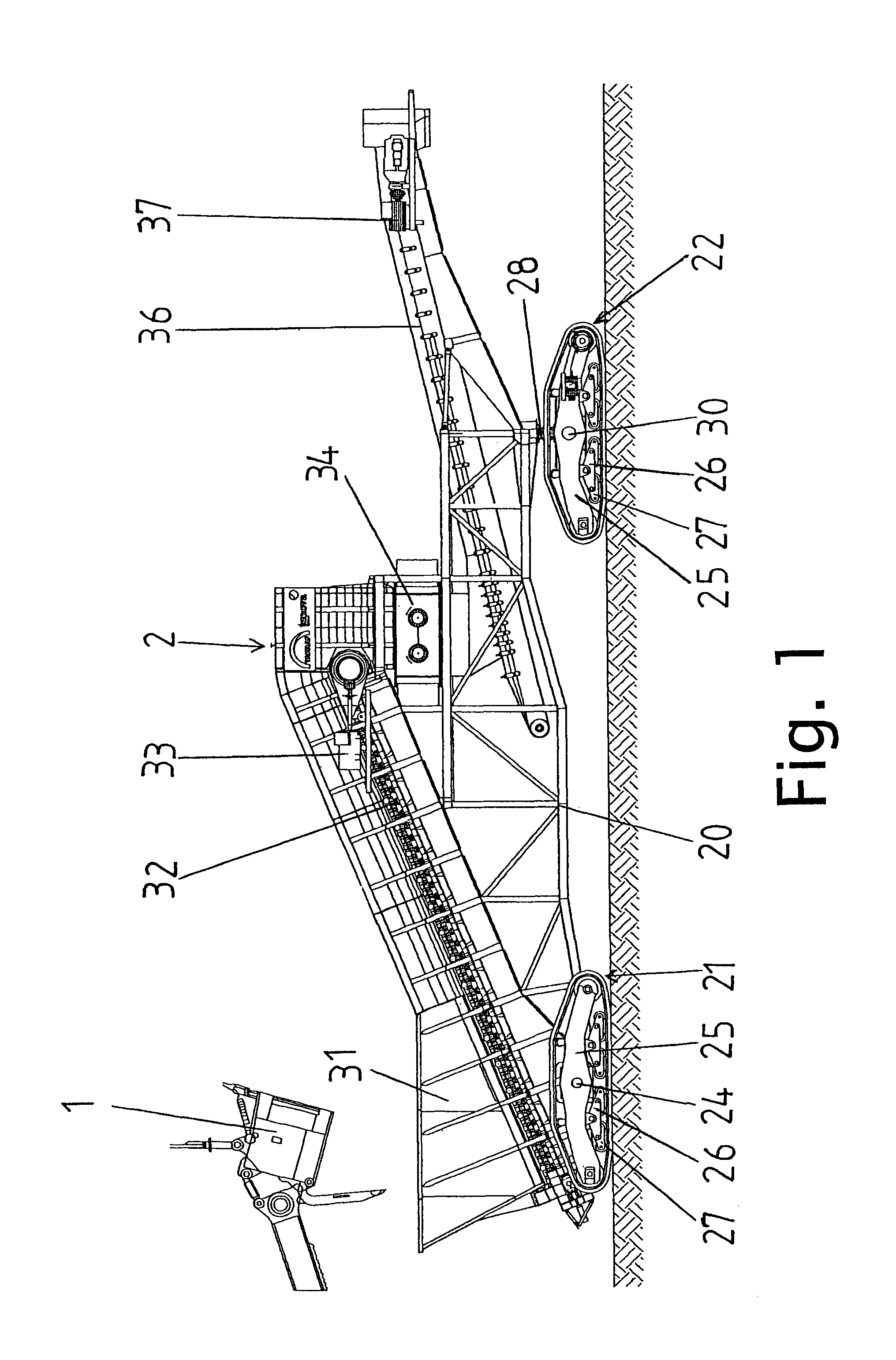
[0036]Referring to the drawings in particular, according to FIG. 1, material is fed from the shovel 1 of a shovel excavator to the mobile crusher 2, pulverized by same to a conveyable size and then transferred to a transfer conveyor (not shown) or a mobile bridge (likewise not shown) for further conveying to the face conveyor. In this case, the mobile crusher 2 and the conveyor arranged downstream are moved further progressively with the mining progress of the shovel excavator.

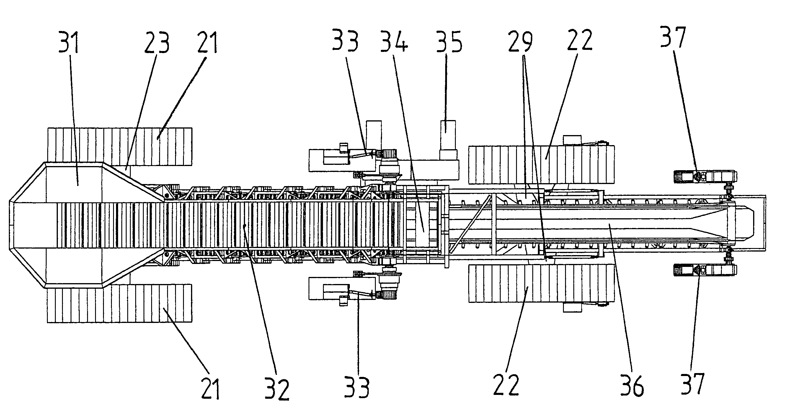
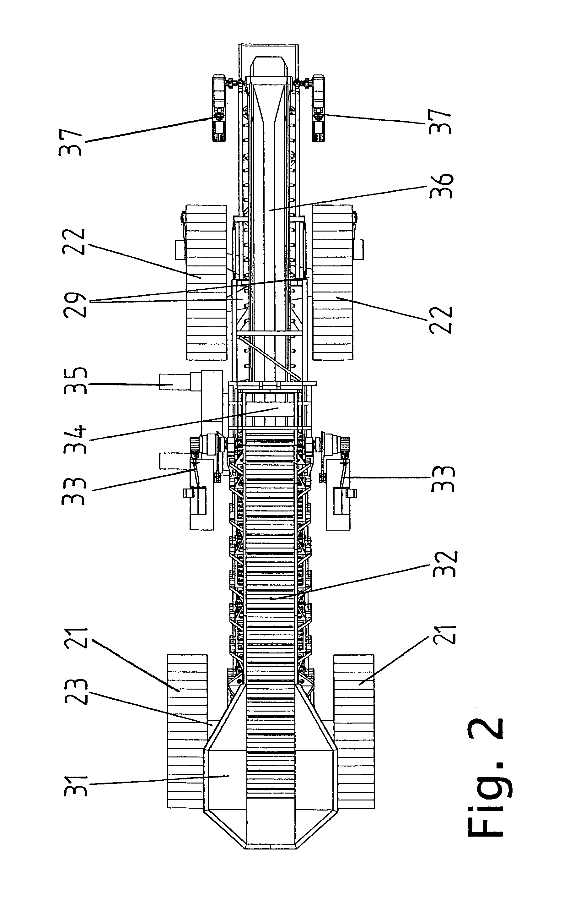
[0037]The mobile crusher 2 consists of a stable supporting frame 20, which is carried by the two rear longitudinal caterpillars (crawlers) 21 and the two front longitudinal caterpillars (crawlers) 22. The supporting frame 20 includes two vertical support panels arranged parallel to one another, which together with lower and upper cross-ties form a stable construction.

[0038]A stable crossbeam 23, which accommodates a long, continuous caterpillar axle 24, is integrated in the rear, lower part of the supporting f...


PUM


Abstract

A mobile crusher (2) is provided that can be displaced on four caterpillars and that includes a supporting frame (20), a large hopper (31), an apron conveyor (32), a sizer (34) and an intermediate conveyor (36) for use in strip-mining. The material is received by the shovel (1) of a shovel excavator or a wheel loader, is fed to the crusher (2), crushed and is then transferred onto a conveyor plant via a discharge conveyor system. The crusher (2) has to follow at the same cycle in which the shovel excavator moves forward during an advance in mining. In order to obtain a good maneuverability of the crusher (2), the two front caterpillars (22) are driven and can be steered like a two-caterpillar chassis. As the crusher (2) is subject to high loads, all components have to have a robust design. For this purpose, the individual functional groups are accommodated in a stable supporting frame (20). The crushed material is transferred onto a subsequent bench conveyor via an evolving conveyor directly connected to the mobile crusher (2), a transfer conveyor or a mobile bridge. The plant can be displaced while under full useful load.

Description

CROSS REFERENCE TO RELATED APPLICATIONS[0001]This application is a United States National Phase application of International Application PCT / DE2010 / 000387 and claims the benefit of priority under 35 U.S.C. §119 of German Patent Application DE 10 2009 016 405.7 filed Apr. 4, 2009 and German Patent Application DE 10 2010 013 154.7 filed Mar. 27, 2010, the entire contents of which are incorporated herein by reference.FIELD OF THE INVENTION[0002]The present invention pertains to a mobile crusher that can be displaced on four caterpillars (also known as caterpillar chassis, crawler undercarriages and continuous track chassis) and that has a supporting frame, a receiving hopper, a hopper transfer belt conveyor, a crusher (crusher unit) and an intermediate conveyor for use in strip mining. The material is received by a shovel excavator or wheel loader, fed to the crusher, crushed there and then transferred onto a downstream conveyor belt unit via a discharge conveyor system with transfer c...

Claims


Application Information

Patent Timeline
Patent Type & Authority Patents(United States)
IPC IPC(8): B02C21/02
CPCB02C21/026
Inventor HUBRICH, FRANKHOFFMANN, DIETER
Owner TAKRAF
Why Eureka
Try Eureka