
Pump unit with a pump and a hybrid drive

a hybrid drive and pump technology, applied in the field of pump units, can solve the problems of small additional space needed for the electric motor and the small space occupied by the pump unit as a whole, and achieve the effects of reducing the overall efficiency of the hybrid unit, reducing the speed of the pump shaft, and increasing the overall efficiency

Active Publication Date: 2014-11-04
ZF FRIEDRICHSHAFEN AG
View PDF12 Cites 2 Cited by
  • Summary
  • Abstract
  • Description
  • Claims
  • Application Information

AI Technical Summary

Benefits of technology

[0008]Thus, the purpose of the present invention is to indicate a pump unit of the type mentioned at the start, which provides a supply of the medium to be delivered according to need and which can be produced in a simple and compact manner.

Problems solved by technology

Consequently only a little additional space is needed for the electric motor, and the space occupied by the pump unit as a whole is therefore very small.

Method used


Image

  • Pump unit with a pump and a hybrid drive
  • Pump unit with a pump and a hybrid drive

Examples


Embodiment Construction

[0031]Particular features of the example embodiments explained in more detail below can also be regarded, in their own right, as an invention or as part of an object of an invention.

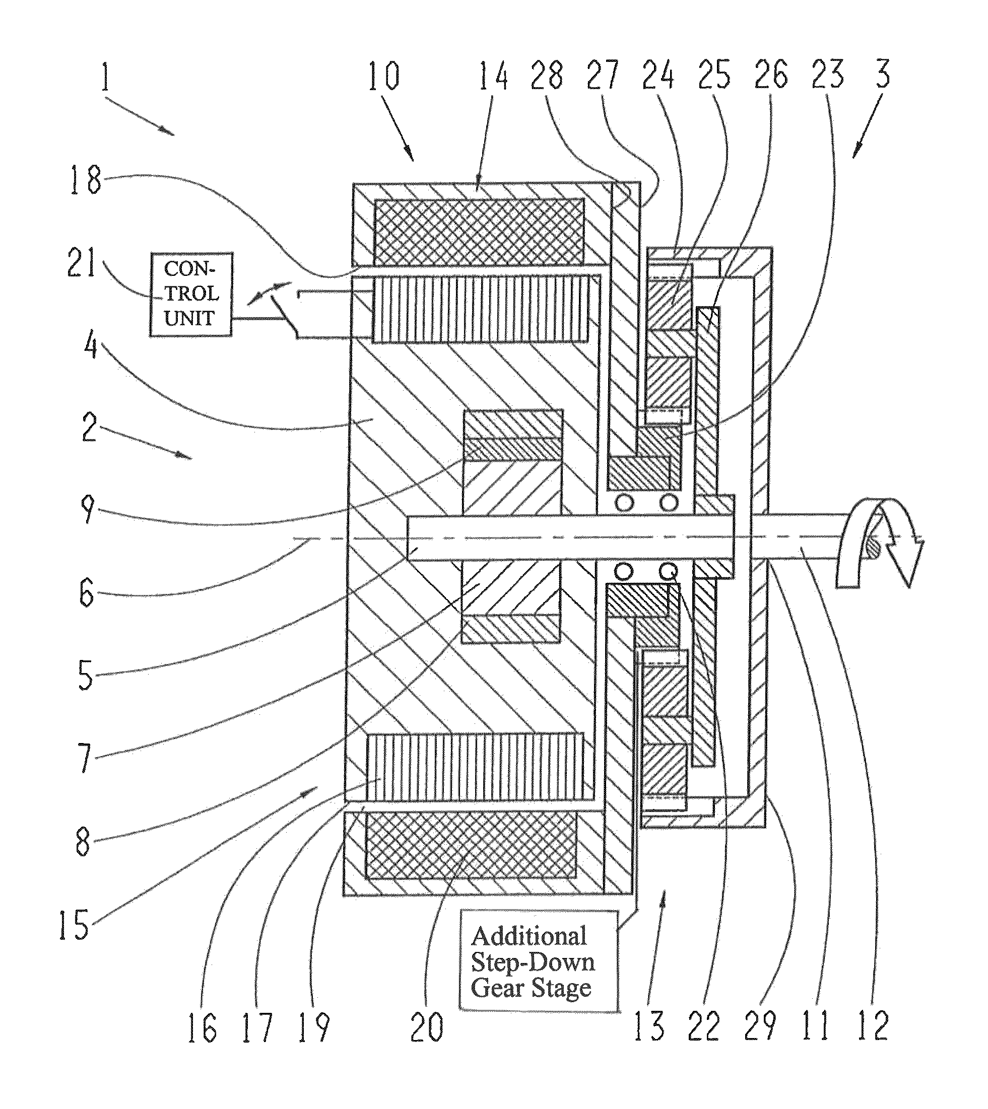
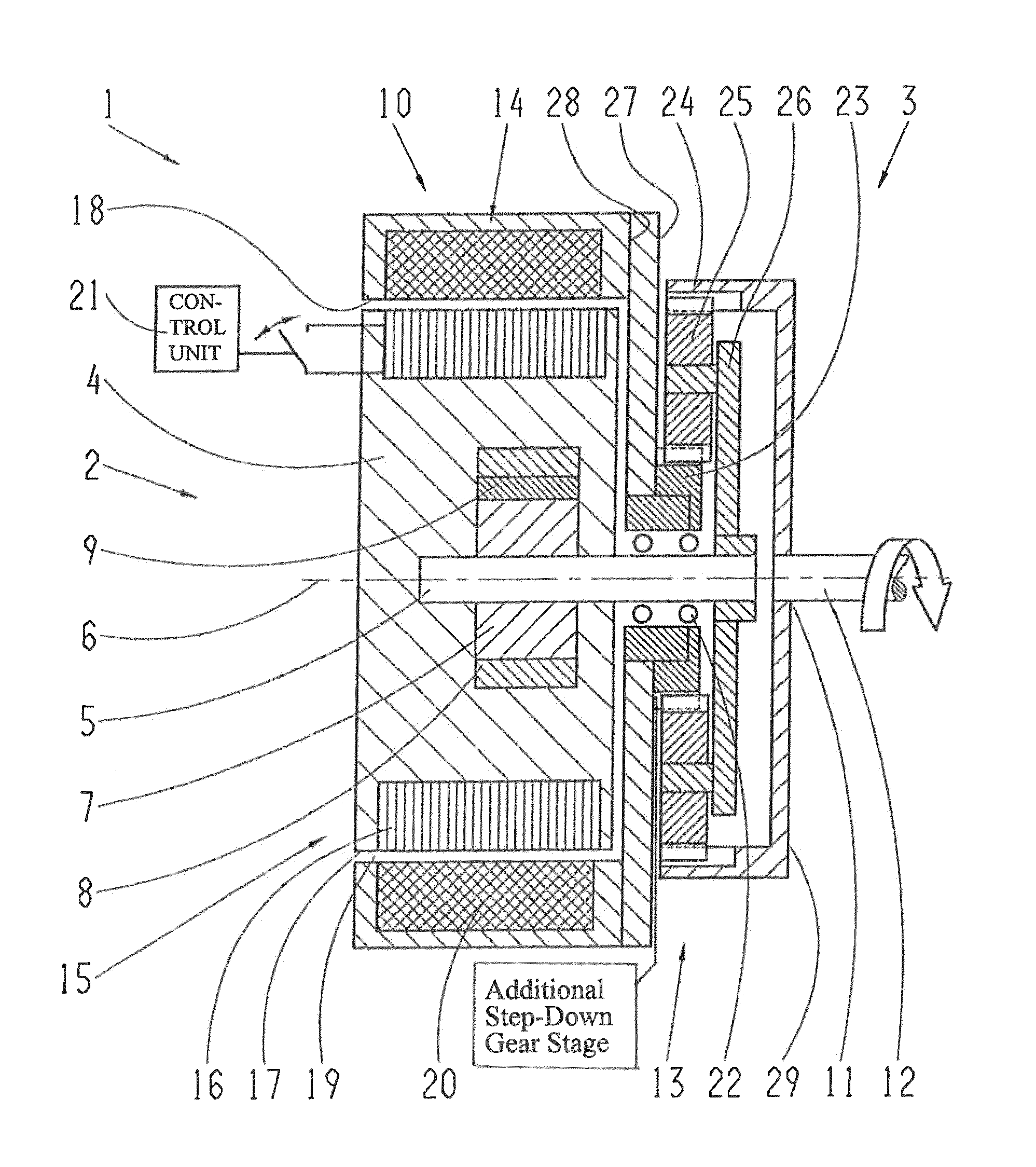
[0032]The example embodiment of a pump unit 1 shown in the FIGURE is in particular a highly integrated hybrid pump for supplying oil to an automatic transmission of a motor vehicle as needed. The pump unit 1 has as its main components a pump in the form of a hydraulic pump 2 and a hybrid drive 3.

[0033]The hydraulic pump 2 has a fixed pump housing 4 in which a pump shaft 5 is mounted to rotate about a rotational axis 6. The pump housing 4 accommodates a pump impeller wheel 7 that can be rotated by means of the pump shaft 5. In addition the hydraulic pump 2 comprises a pump ring gear 8 and a sickle 9. When the pump impeller wheel 7 rotates, oil is fed in an oil volume flow into a duct (not shown) leading it away, from where the oil is passed on into the transmission. The hydraulic pump 2 is a fixed-displac...


PUM


Abstract

The pump unit has a pump and a hybrid drive. The pump comprises a pump housing and a pump shaft. The hybrid drive comprises an electric motor and a driveshaft connection to a driveshaft. The electric motor and the driveshaft connection are each in driving mechanical functional connection with the pump shaft by way of a planetary gearset for driving the pump shaft. A stator of the electric motor is at least partially integrated in the pump housing. A rotor of the electric motor is mechanically connected fixed to a sun gear of the planetary gearset. The driveshaft connection is mechanically connected fixed to a ring gear of the planetary gearset. The pump shaft is mechanically connected fixed to a planetary carrier of the planetary gearset.

Description

[0001]This application claims priority from German patent application serial no. 10 2011 088 060.7 filed Dec. 9, 2011.FIELD OF THE INVENTION[0002]The invention concerns a pump unit, in particular of a vehicle transmission, with a pump and a hybrid drive, such that the pump comprises a pump housing and a pump shaft and the hybrid drive comprises an electric motor and a driveshaft connection on a driveshaft.BACKGROUND OF THE INVENTION[0003]Such a pump unit is used for example in an automatic transmission of a motor vehicle for supplying hydraulic oil. In particular, it is driven by the internal combustion engine so that the quantity of hydraulic oil delivered is governed by the running speed of the internal combustion engine. The geometric pump volume is usually designed with regard to the idling speed. Since the volume delivered increases with the running speed, in the upper speed range such a pump often delivers too much oil. On the one hand this leads to unnecessary energy consumpt...

Claims


Application Information

Patent Timeline
Patent Type & Authority Patents(United States)
IPC IPC(8): F16H37/06
CPCF16H61/0028F16H37/065F16H57/0439F16H37/0826
Inventor RIEGERT, GERNOTZWICK, RAPHAELHARSCHER, MARIO
Owner ZF FRIEDRICHSHAFEN AG
Learn More