Belt unit and image forming apparatus

a technology of image forming apparatus and belt unit, which is applied in the direction of electrographic process apparatus, instruments, optics, etc., can solve the problems of character skew, image stretch, color deviation, and the guide rib disposed in the endless belt is likely to overrun the driving roller for an extended time, so as to prevent the meandering of the endless belt

Active Publication Date: 2014-11-11
SHARP KK
View PDF15 Cites 2 Cited by
  • Summary
  • Abstract
  • Description
  • Claims
  • Application Information

AI Technical Summary

Benefits of technology

[0009]The driving roller is disposed on an inner peripheral surface side of the endless belt and drives the endless belt. The pair of guide ribs is placed on each opposite widthwise end of the inner peripheral surface of the endless belt and contacts both end faces of the driving roller, thus preventing meandering of the endless belt. Additionally, the driving roller is equipped with a low friction region at both opposite lengthwise ends in a predetermined width and the low friction region is configured to have a friction coefficient that is lower than a friction coefficient of a region adjacent to the low friction region.
[0010]With this configuration, even if the guide ribs overrun on the driving roller, since the frictional force generated between the guide ribs and a low friction region is small, the guide ribs return to a position in which each of the guide ribs contacts an end face of the driving roller by sliding toward the end face of the driving roller. Therefore, the guide ribs can be is prevented from overrunning on the driving roller for an extended time.

Problems solved by technology

In recent years, however, improvement in the speed and colorization of copying machines, laser beam printers (LBP), and the like has been developed, so that the above mentioned driving rollers with the endless belt, due to the variation in the speed of feeding the endless belt by the driving roller and the irregularities of the surface of the endless belt, have problems such as character skew, image stretch, and color deviation.
However, in Japanese Laid-Open Patent Publication 2010-152063, a guide rib disposed in the endless belt is likely to overrun on the driving roller for an extended time.

Method used


Image

  • Belt unit and image forming apparatus
  • Belt unit and image forming apparatus
  • Belt unit and image forming apparatus

Examples


first embodiment

[0026]To begin with, description will be made of the present invention.

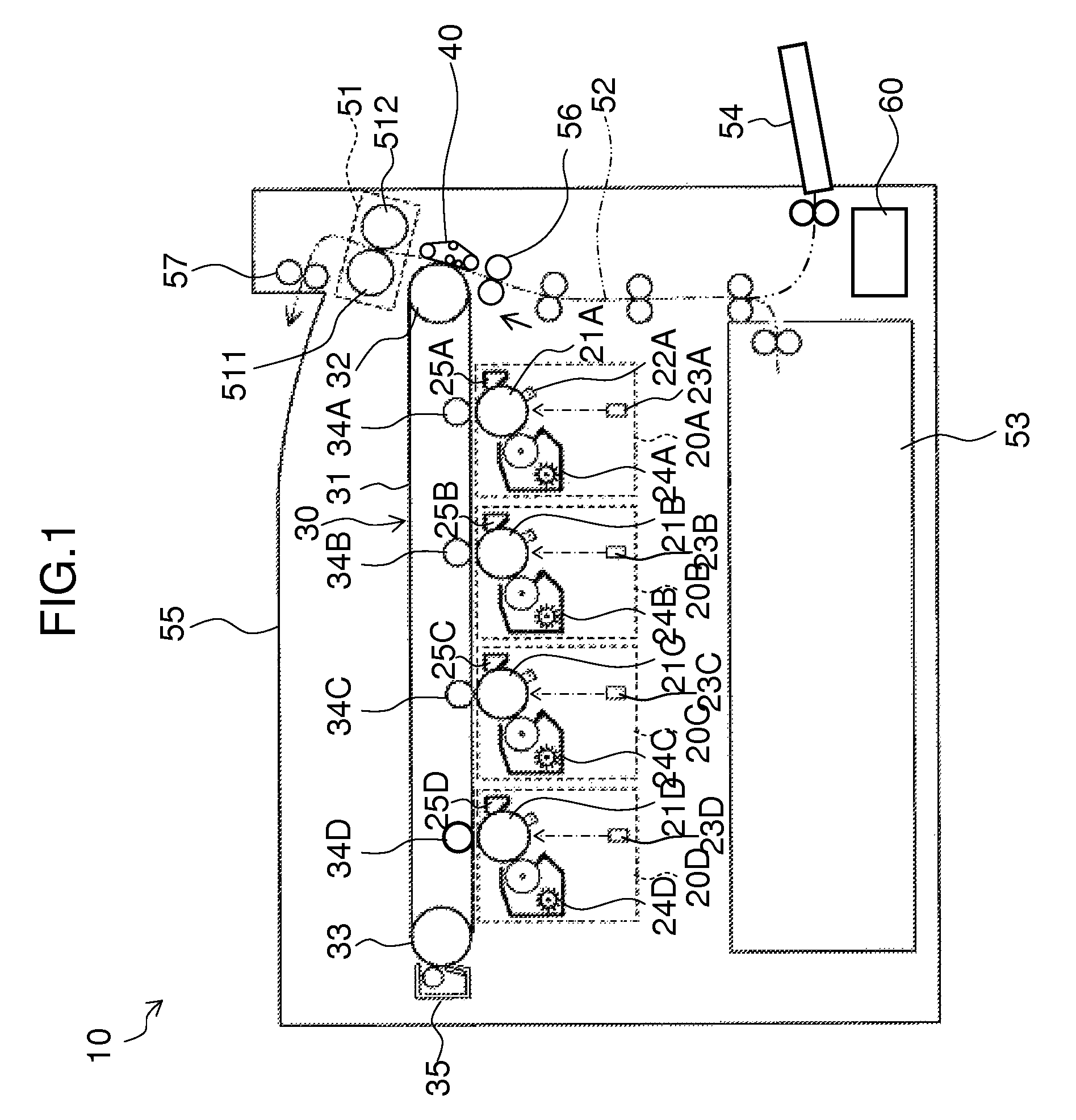
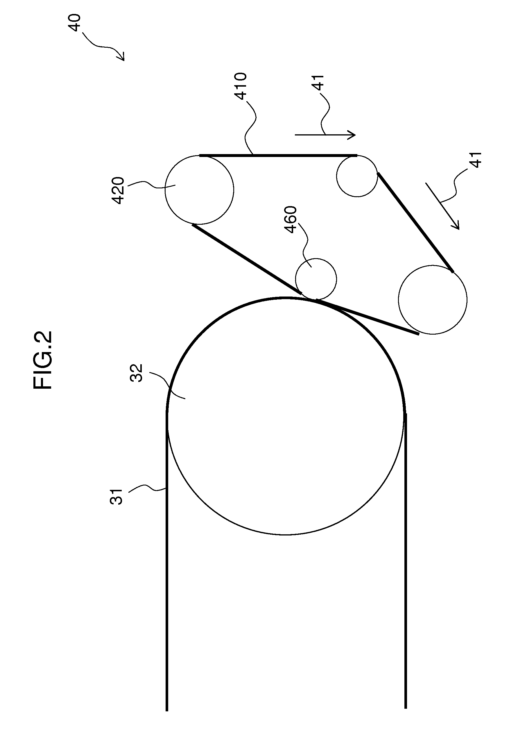
[0027]FIG. 1 is a front view of a configuration of an image forming apparatus 10 that is equipped with a secondary transfer belt unit 40 according to the first embodiment of the present invention.

[0028]The image forming apparatus 10 is provided with a plurality of image forming portions 20A, 20B, 20C, and 20D, a primary transfer unit 30, a secondary transfer belt unit 40, a fixing unit 51, a paper feed path 52, a sheet feed cassette 53, a manual feed tray 54, a paper output tray 55, and a control portion 60. The control portion 60 controls each part of the image forming apparatus 10 in an integrated manner.

[0029]The image forming apparatus 10 carries out an electrophotographic image forming process using image data corresponding to four colors: black and the three subtractive primary colors, that is, cyan, magenta and yellow, obtained by color separation of a color image. The image forming portions 20A to 20D are...

third embodiment

[0062]Subsequently, description will be made of the present invention.

[0063]FIG. 6 is a side elevational view of the configuration of the secondary transfer belt unit 40 according to the third is embodiment of the present invention.

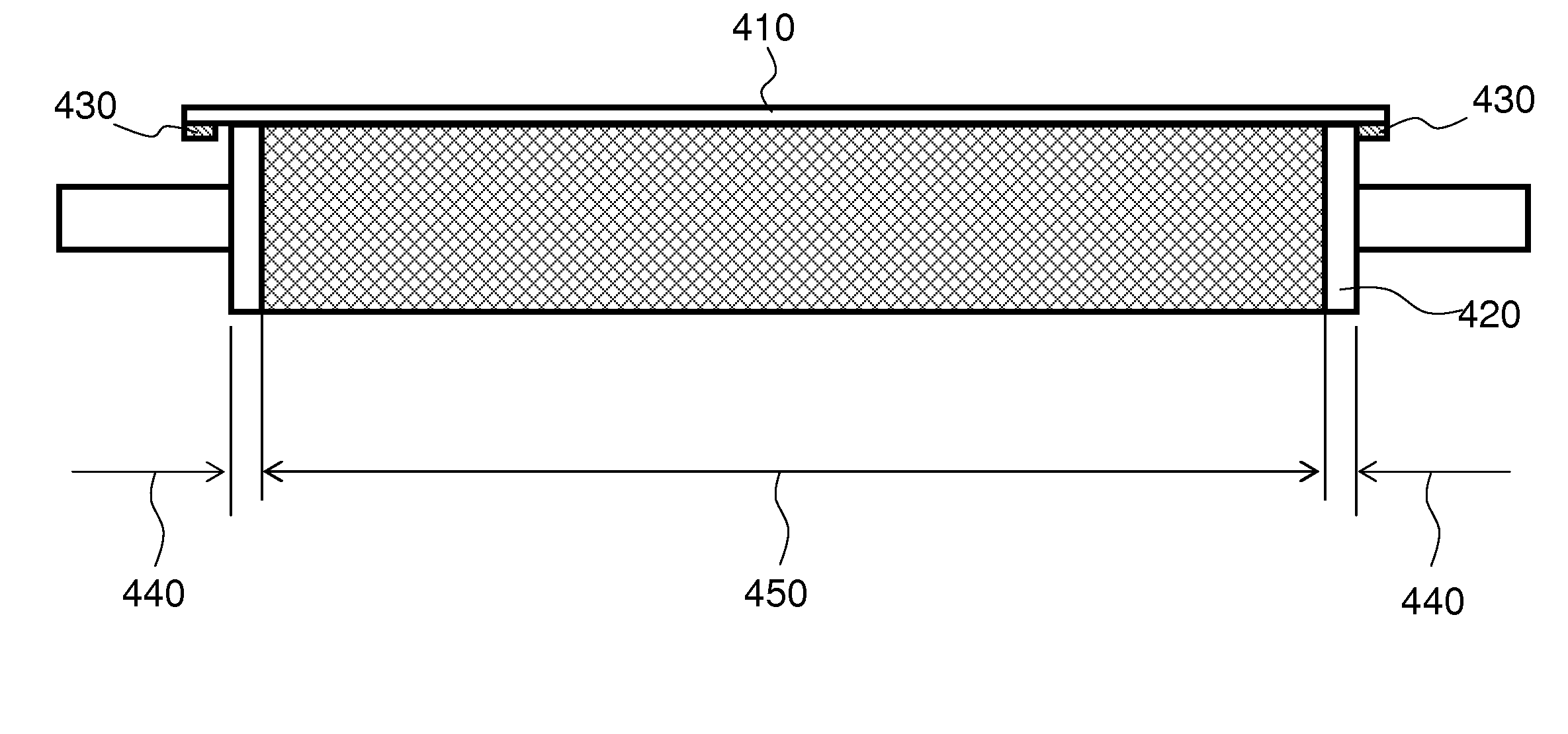
[0064]The secondary transfer belt unit 40 may preferably include elastic rubber 470. The elastic rubber 470 may preferably be wound around the entirety of the outer peripheral surface of the driving roller 420. Additionally, the elastic rubber 470 has a first region 480 corresponding to the low friction region 440 of the driving roller 420 and a second region 490 corresponding to all other regions: the first region 480 is mirror finished and the second region 490 has a friction coefficient that is higher than a friction coefficient of the first region 480.

[0065]Thus, by winding the elastic rubber 470 around the entirety of the driving roller 420, no uneven level is created in the entirety of the driving roller.

[0066]With this configuration, since the elas...

fourth embodiment

[0069]Subsequently, description will be made of the present invention.

[0070]FIG. 7 is a side elevational view of a configuration of the driving roller 420 in the secondary transfer belt unit 40 according to the fourth embodiment of the present invention. FIG. 8 is a side elevational view of the configuration of the secondary transfer belt unit 40 according to the fourth embodiment of the present invention. FIG. 9 is a sectional side elevational view of the configuration of the secondary transfer belt unit 40 according to the fourth embodiment of the present invention.

[0071]The driving roller 420 may preferably have a recessed portion on the outer peripheral surface (a region 450) other than the low friction region 440, the recessed portion having a volume equal to the elastic rubber 470. The elastic rubber 470 may also be wound around the recessed portion of the driving roller 420. The low friction region 440 of the driving roller 420 may be configured to have an external diameter t...


PUM


Abstract

A belt unit is provided with an endless belt, a driving roller, and a pair of guide ribs. The driving roller is disposed on an inner peripheral surface side of the endless belt and drives the endless belt. The pair of guide ribs is placed on each opposite widthwise end of the inner peripheral surface of the endless belt and contacts both end faces of the driving roller, thus preventing meandering of the endless belt. Additionally, the driving roller is equipped with a low friction region at both opposite lengthwise ends in a predetermined width and the low friction region is configured to have a friction coefficient that is lower than a friction coefficient of a region adjacent to the low friction region.

Description

CROSS REFERENCE[0001]This Nonprovisional application claims priority under 35 U.S.C. §119(a) on Patent Application No. 2011-252453 filed in Japan on Nov. 18, 2011, the entire contents of which are hereby incorporated by reference.BACKGROUND OF THE INVENTION[0002]The present invention relates to a belt unit capable of enhancing the meandering prevention of an endless belt and also to an image forming apparatus equipped with the belt unit.[0003]Conventionally, as driving rollers that drive an endless belt used for equipment such as OA (Office Automation) equipment, is for example, driving rollers that include a roller body and elastic rubber that wound around the surface of the roller body had been known.[0004]In recent years, however, improvement in the speed and colorization of copying machines, laser beam printers (LBP), and the like has been developed, so that the above mentioned driving rollers with the endless belt, due to the variation in the speed of feeding the endless belt b...

Claims


Application Information

Patent Timeline
Patent Type & Authority Patents(United States)
IPC IPC(8): B65G15/46G03G15/16
CPCG03G2215/0132B65G15/46G03G2215/00151G03G15/1615G03G2215/00168G03G15/2053B65G15/30G03G15/16B65G23/04
Inventor MIZOGUCHI, FUMITOHIRAI, MASASHITAKIGUCHI, TOSHIKI
Owner SHARP KK
Why Eureka
Try Eureka