Boot for covering ball joint

a ball joint and boot technology, applied in the field of boots, can solve the problems of difficult to recover to an original shape the description of the steering boot, and the malfunction of the steering boot b>100/b>, and achieve the effect of low cost and restraint of meandering

Inactive Publication Date: 2007-11-20
TOYODA GOSEI CO LTD
View PDF10 Cites 2 Cited by
  • Summary
  • Abstract
  • Description
  • Claims
  • Application Information

AI Technical Summary

Benefits of technology

[0010]That is, the boot of the invention is arranged with the first bellows portion making the rigidity in a radial direction higher than that of the second bellows portion while maintaining an axial direction rigidity thereof to a degree equivalent to that of the second bellows portion. According to the boot of the invention, meandering can be restrained by comparatively simple means of changing the inner peripheral diameter of the bellows portion. Therefore, a number of steps of working a die is small and cost is low. Further, according to the boot of the invention, the first bellows portion is difficult to deform by increasing the rigidity in a radial direction while maintaining the axial direction rigidity and therefore, the first bellows portion is difficult to be brought into sliding contact with a clamp of the larger diameter attachment portion.
[0015]In this way, according to the constitution, the first bellows portion can be restrained from being deformed by the high rigidity of its own and the second bellows portion can be restrained from being deformed by being brought into contact with the ball joint, respectively. Therefore, not only meandering of the first bellows portion but also meandering of the second bellows portion can be restrained.
[0018](5) Preferably, there may be constructed a constitution in which an end portion of the ball joint is contained in the taper bellows portion in the above-described constitution of (3). According to the constitution, the taper bellows portion is brought into contact with the end portion of the ball joint soon after starting to deform. The taper bellows portion is not deformed further by being restrained by the ball joint. According to the invention, not only meandering of the first bellows portion and the second bellows portion but also meandering of the taper bellows portion can be restrained.
[0019]According to the invention, there can be provided the boot in which a number of steps of working the die is small, the cost is low and meandering can be restrained by arranging the first bellows portion increasing the rigidity in a radial direction continuous to the large diameter attachment portion while maintaining the axial direction rigidity to a degree equivalent to that of the second bellows portion.BRIEF DESCRIPTION OF THE DRAWINGS

Problems solved by technology

Therefore, there is a concern that the steering boot 100 malfunctions.
Therefore, once the steering boot 100 meanders to deform, even when the steering boot 100 is cooled, the steering boot 100 is difficult to recover to an original shape.
Therefore, the steering boot described in the reference is difficult to meander.
Therefore, according to the steering boot described in the reference, a number of steps of working a die is large and cost is high.
Further, by providing the peripheral groove at the bottom portion of the bellows, a rigidity in a direction of elongating and contracting the bellows is reduced and there is a possibility that a portion thereof which meanders to deform is liable to interfere with the clamp fixedly attached to the end of the steering gear box.
Further, according to the boot of the invention, the first bellows portion is difficult to deform by increasing the rigidity in a radial direction while maintaining the axial direction rigidity and therefore, the first bellows portion is difficult to be brought into sliding contact with a clamp of the larger diameter attachment portion.
That is, because when both of the first bellows portion and the second bellows portion are provided with high rigidities, a function of being elongated and contracted and bent inherent to the bellows is deteriorated.
Further, both of the first bellows portion and the second bellows portion are provided with low rigidities, the above-described meandering is liable to be brought about.
On the other hand, the inner peripheral diameter of the first bellows portion is set to the bottom inner peripheral diameter of the second bellows portion multiplied by the multiplication factor equal to or smaller than 1.3 because when the multiplication factor exceeds 1.3, the difference between the diameters is excessively increased and there is a concern that the first bellows portion does not achieve the function of being elongated and contracted and bent inherent to the bellows.
Further, because pivotal movement of the ball joint is excessively restrained by interference with the second bellows portion.
That is, because meandering cannot sufficiently be restrained.

Method used


Image

  • Boot for covering ball joint
  • Boot for covering ball joint
  • Boot for covering ball joint

Examples


Embodiment Construction

[0024]An explanation will be given of a steering boot (hereinafter, abbreviated as “boot”) according to an embodiment of a boot of the invention as follows.

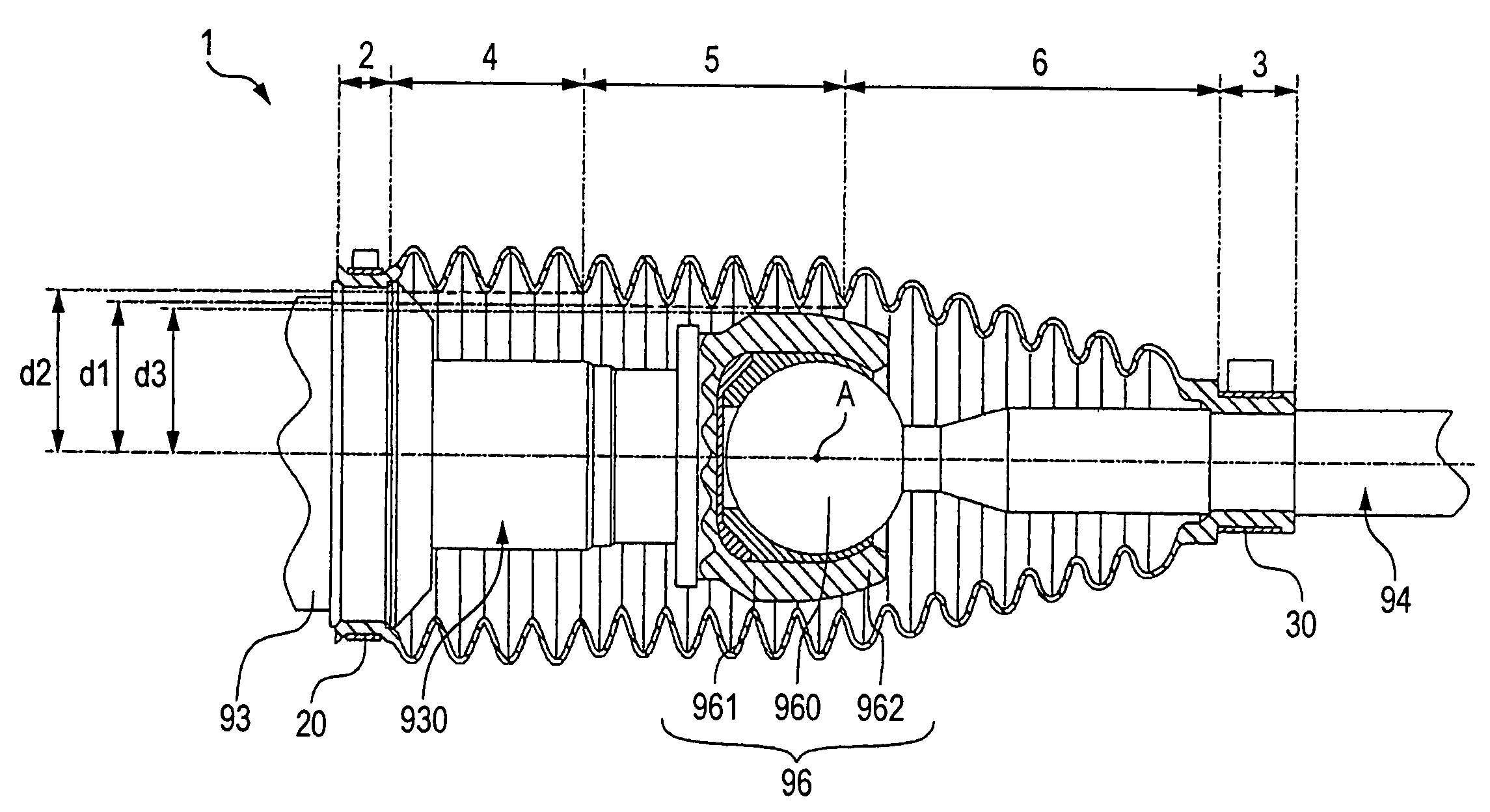
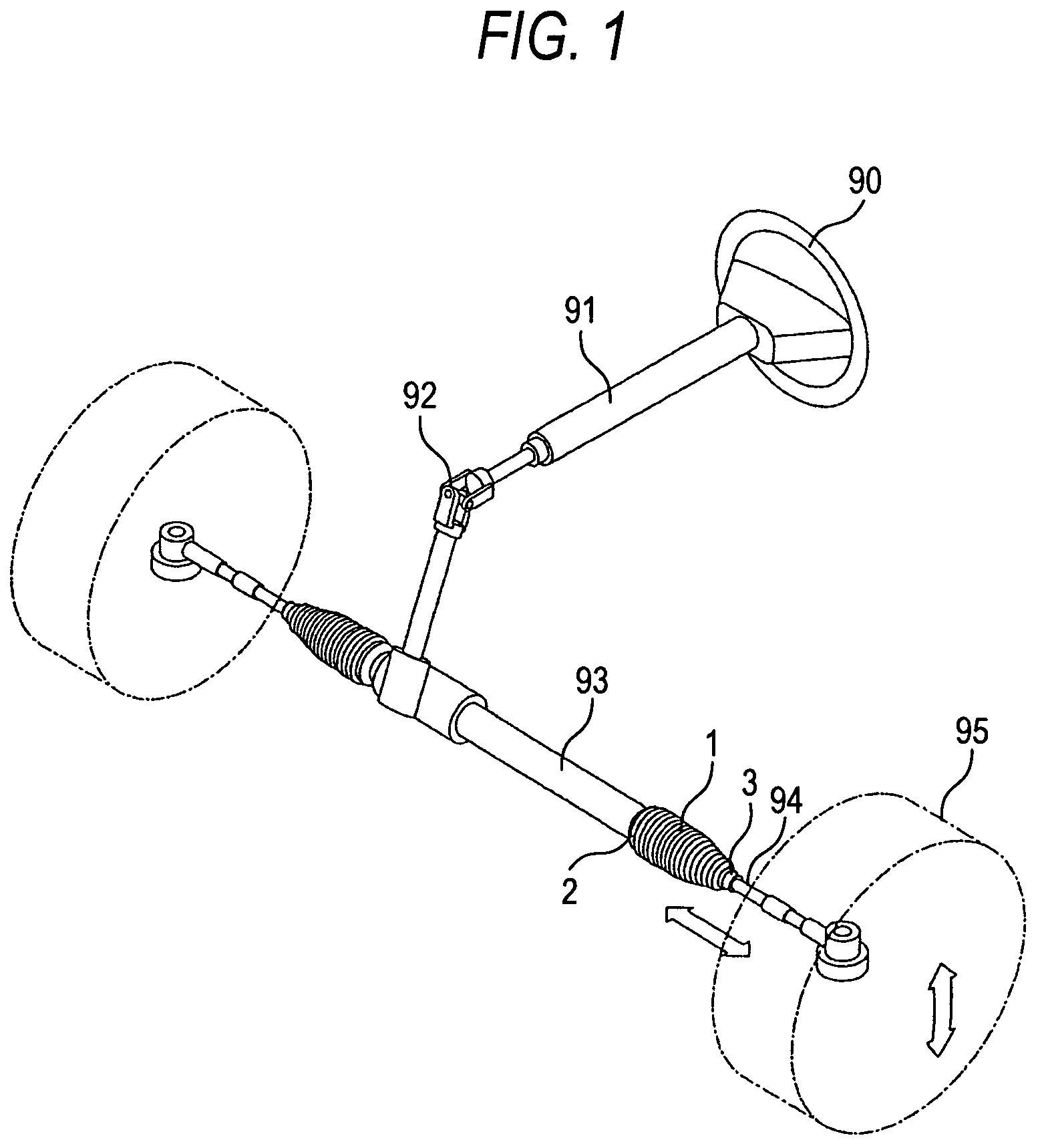
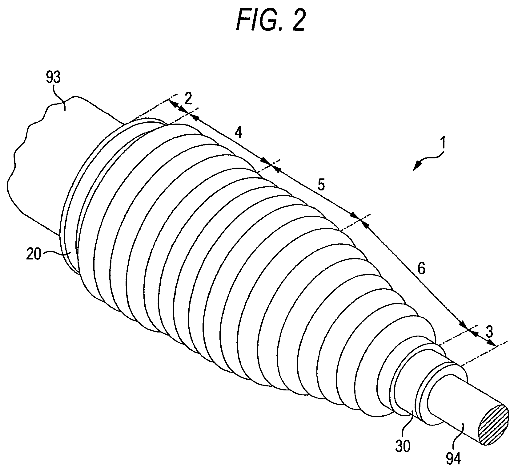
[0025]First, an explanation will be given of a position of attaching a boot according to the embodiment. FIG. 1 shows a view of attaching a boot according to the embodiment. As shown by the drawing, a steering wheel 90 is connected to a steering column 91. The steering column 91 is connected to a pinion (not illustrated) included in a steering gear box 93 via a universal joint 92. The pinion is brought in mesh with a rack (not illustrated) similarly included in the steering gear box 93. An end of the rack and a tie rod 94 are connected via a ball joint (not illustrated). The ball joint is covered by a boot 1.

[0026]When a driver turns the steering wheel 90, a turning force is transmitted to the pinion via the steering column 91 and the universal joint 92. The pinion is brought in mesh with the rack. Therefore, by rotationally movi...


PUM


Abstract

A boot is made of a resin for covering a ball joint interposed between a larger diameter mating member and a small diameter mating member, including a large diameter attachment portion fixed to the large diameter mating member, a first bellows portion continuous to the large diameter attachment portion, a second bellows portion which is continuous to the first bellows portion and in which at least a bottom inner peripheral diameter thereof is not larger than that of the first bellows portion and a rigidity in a radial direction thereof is lower than that of the first bellows portion, a taper bellows portion continuous to the second bellows portion, and a small diameter attachment portion continuous to the taper bellows portion and fixed to the small diameter mating member.

Description

BACKGROUND OF THE INVENTION[0001]1. Field of the Invention[0002]The present invention relates to a boot attached to, for example, a steering apparatus of a rack pinion type steering or the like.[0003]2. Related Art[0004]A steering boot covers a ball joint between a steering gear box and a tie rod. That is, one end of the steering boot is fixedly attached to an end of a steering gear box. Further, the other end of the steering boot is fixedly attached to the tie rod. The steering boot is arranged to be proximate to an engine. Therefore, an environmental temperature at a vicinity of the steering boot is a comparatively high temperature. Therefore, air hermetically sealed inside of the steering boot is expanded.[0005]FIG. 4 shows a side view in an axial direction of a steering boot. As shown by the drawing, when air at inside of the steering boot 100 is expanded, the steering boot 100 is expanded to deform. Further, the steering boot 100 meanders to wave in an S-like shape between an e...

Claims


Application Information

Patent Timeline
Patent Type & Authority Patents(United States)
IPC IPC(8): F16J3/00F16J15/52F16L51/02F16D3/84F16J3/04
CPCF16J3/041Y10T403/31
Inventor OTA, KATSUHISA
Owner TOYODA GOSEI CO LTD
Why Eureka
Try Eureka