
Magnetic stimulation coils with electrically conducting structures

a technology of electrical conductivity and magnetic stimulation coil, which is applied in the field of biological tissue stimulation, can solve the problems of discomfort for the patient and the operator of the coil, the disadvantages of conventional tms coils, and the inability to heat up very easily, so as to improve the rigidity of the coil structure, improve the comfort of users, and transfer heat

Inactive Publication Date: 2014-11-11
NEXSTIM
View PDF9 Cites 0 Cited by
  • Summary
  • Abstract
  • Description
  • Claims
  • Application Information

AI Technical Summary

Benefits of technology

[0028]Considerable advantages are gained with the aid of the invention. The possibility to use metals near the coil windings offers new opportunities for transferring heat dissipated in the stimulator coil efficiently away from the coil windings. This leads to lower peak temperature on the surface of the coil casing, which is to be placed in contact with the patient's head, improving user comfort significantly. Moreover, the use of metals near the coil windings can offer improved rigidity in the coil structures.
[0029]According to one embodiment of the invention, further advantages can be gained by having a cooling structure without circulating heat transfer fluid and the necessary auxiliary components, such as blower fans causing excess noise. This way the structure of the device becomes more robust and reliable as well as lighter, which is beneficial in terms of operator ergonomics. The simpler construction is also inexpensive and quick to manufacture due to minimized variety of parts. In addition, since there is no heat transfer fluid involved, there is no risk of spillage or seepage of cooling liquid onto the patient, nor is there a need for liquid change, which has an improving effect on maintenance intervals.
[0030]According to another embodiment of the invention, the device may have parts of the casing made of electrically conducting and non-magnetic material, such as metals like copper or silver and plastics or ceramics. There is therefore an additional advantage of precise and accurate manufacturing of the product as well as being able to construct a rigid structure supported by the metallic elements.

Problems solved by technology

However, conventional TMS coils feature considerable disadvantages.
An essential problem is that they heat up very easily due to high current peaks at relatively high repetition rates.
The heat problem causes discomfort for the patient and operator of the coil.
The strong current pulse with peak of several kiloamps results in ohmic losses and corresponding Joule heating in the resistive coil.
However, the coil must be light and small also for usability improvement purposes, since the operator may have to handle the coil for rather long periods of time.
Accordingly, adding extra weight to the device is not advantageous.
Another problem with this solution is that plastic conducts heat slowly and the heat capacity of plastics is rather low compared to more progressive cooling means.
However, the use of liquid coolants makes the device considerably complex and creates a risk of spilling the coolant on the patient in the event of a broken coil casing.
Another problem with liquids is that they conduct heat relatively poorly from the coil to its surroundings.
Air-cooling is not preferred either, because of increased complexity and also excess noise emanating from the necessary cooling blowers.
However, metals have not been used in close proximity of TMS coils, because the changing magnetic field of the coil induces eddy currents in metals that will heat them up.
The force can create a considerable risk and break the construction.
The force also causes loud audible noise pulses, which are harmful for occupants of the operating room.
Currently there are no known coil solutions featuring electrically conducting non-ferromagnetic material in the immediate vicinity of the coil coppers.

Method used


Image

  • Magnetic stimulation coils with electrically conducting structures
  • Magnetic stimulation coils with electrically conducting structures
  • Magnetic stimulation coils with electrically conducting structures

Examples


Embodiment Construction

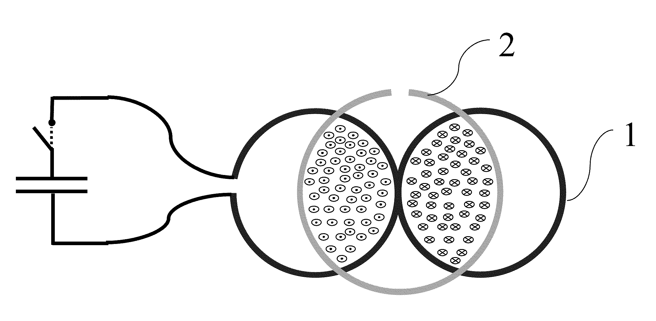
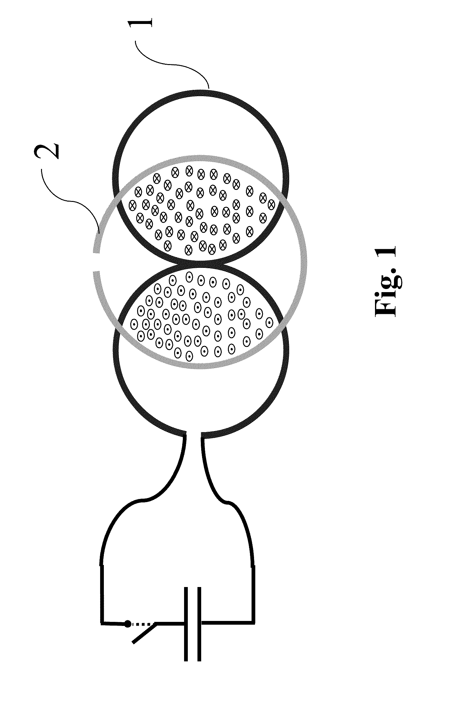
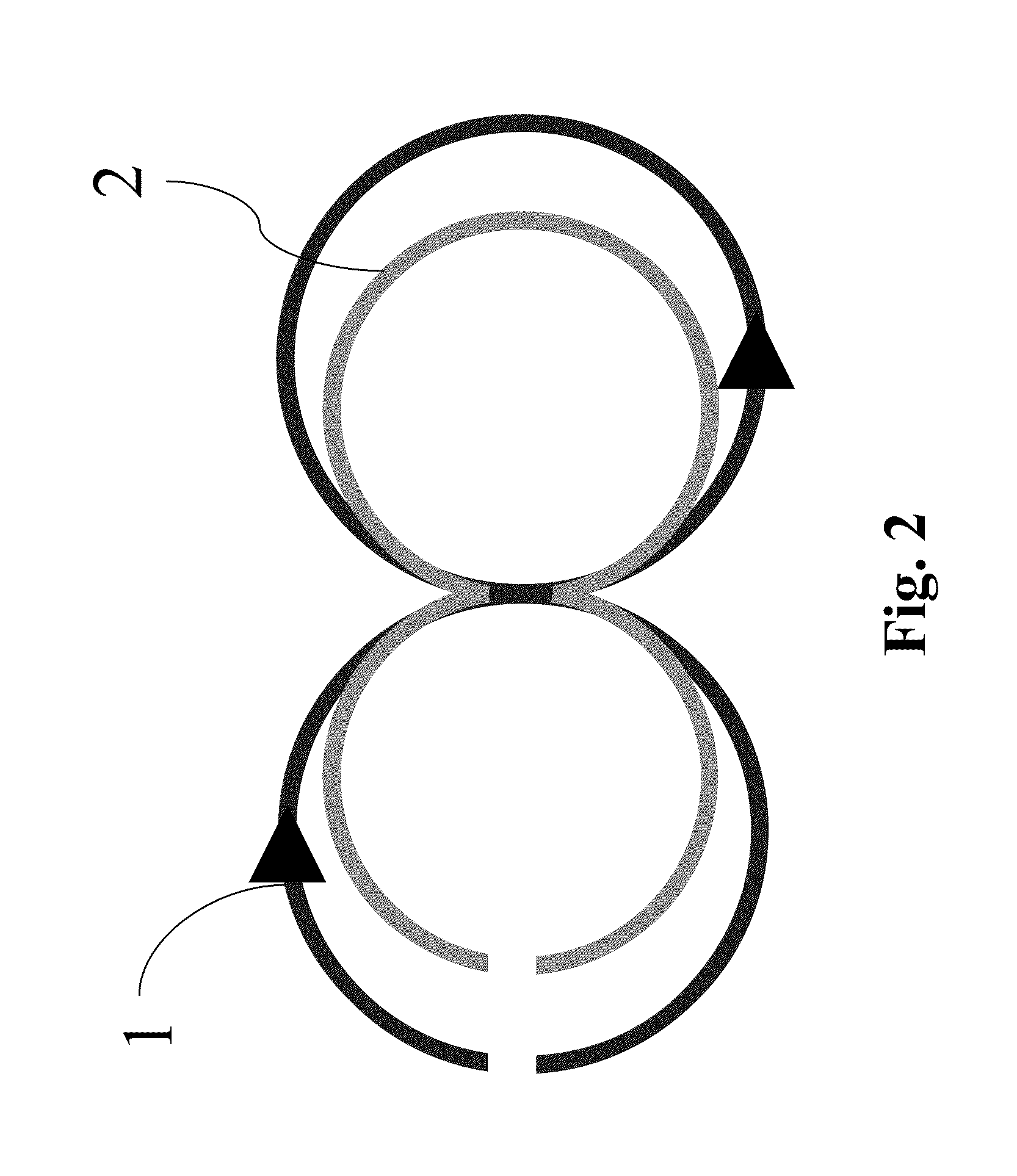
[0037]According to the present invention, it is possible to provide a magnetic stimulator coil with metallic cooling elements. The cooling constructions are chosen so that the copper windings of the TMS coil have minimal electromagnetic coupling with the electrically conducting cooling and supporting structures. This is achieved when the mutual inductance between the coil and the electrically conducting supporting / cooling piece / pieces is zero or close to zero.

[0038]In principle, the cooling structure can be manufactured of any electrically conducting and non-magnetic material having good thermal properties, i.e., its coefficient of thermal conductivity is high, preferably greater than 10 WK−1m−1, or its heat capacity is high, preferably greater than 1 Jcm−3K−1, or both. Therefore suitable materials for herein described applications include for example copper and silver. By electrically conducting material is meant a material having the electrical conductivity of at least 0.01 MS / m, ...


PUM


Abstract

The present invention introduces a novel apparatus (5) for providing magnetic stimuli to the human brain, the apparatus (5) comprising a casing (4) and at least one coil winding (1) adapted to carry electrical current and enclosed within the casing (4) as well as cooling means (2) situated in thermal connection with the coil (1) and comprising a body made of electrically conductive and non-magnetic material so that the mutual inductance between the coil (1) and the cooling means (2) is essentially zero.

Description

FIELD OF THE INVENTION[0001]The present invention relates to stimulating biological tissue for medical purposes. In particular, the present invention relates to an apparatus for magnetic stimulation including electrically conducting structures. To be precise, the present invention relates to what is stated in the preamble portion of the independent claims.BACKGROUND OF THE INVENTION[0002]Biological tissue, such as the human brain, can be stimulated non-invasively when attempting to diagnose a symptom or to achieve a therapeutic effect. Using conventional techniques, it is possible to stimulate biological tissue by virtue of inducing an electric field in the tissue. The technique of magnetic stimulation accomplishes this by means of brief pulses of changing magnetic field. Various apparatuses and methods for providing biological tissue with magnetic stimulation are disclosed, e.g., in publications:[0003]U.S. Pat. No. 4,940,453[0004]U.S. Pat. No. 5,766,124[0005]U.S. Pat. No. 6,132,361...

Claims


Application Information

Patent Timeline
Patent Type & Authority Patents(United States)
IPC IPC(8): A61N2/02A61N2/00A61B5/05
CPCA61B5/05A61N2/008A61N2/02
Inventor RUOHONEN, JARMO
Owner NEXSTIM
Learn More