Differential mobility spectrometer with asymmetrically oscillating driving electrical field

a technology of driving electrical field and mobility spectrometer, which is applied in the direction of mass spectrometers, instruments, separation processes, etc., can solve the problems of limiting the freedom to choose the values of these parameters, and giving no details on possible variations of longitudinal electric field

Active Publication Date: 2014-11-11
IEE INT ELECTRONICS & ENG SA
View PDF18 Cites 2 Cited by
  • Summary
  • Abstract
  • Description
  • Claims
  • Application Information

AI Technical Summary

Problems solved by technology

Such public applications necessitate millions of individual spectrometers and can only become realistic if such devices can be manufactured at low costs.
In addition, there are technical requirements (e.g. the miniaturization) that limit the freedom to choose the values of these parameters.
The patents however, give no details on possible variations of the longitudinal electric field.
At present, in about 90% of the cases, ionization in DMS devices is provided by β-radioactive sources (such as 63Ni) due to low and easy service requirements, low price and high stability of such sources.
Mass market introduction of such β-source-based devices is, however, hindered by strict law requirements on the one hand and public prejudice against any sort of radioactivity on the other hand.
Due to its intrinsic properties this method leads to a fast contamination of the devices and may be mortal for micro-devices.
In this case, the flash lamp irradiates the mixture of air and analyte within the Ion Mobility Spectrometer, which results in ionization of the mixture.
The nature of the DMS method imposes certain limitations on construction of DMS devices.
This yields r≈100−10>>1. The estimate shows that such a device is unable to give reliable results.
Even a 10-fold increase in filter length up to L=2 mm, yields the resolution factor close to unity r≈1−0.1, which still results in a risky regime of operation.
The above analysis demonstrates that there is limited freedom for varying the parameters of a micro-DMS device in order to decrease r (e.g. by variation of voltages or the inter-electrode distance d).
Considerable increase in L however, imposes problems for the micro-machining of the device.

Method used


Image

  • Differential mobility spectrometer with asymmetrically oscillating driving electrical field
  • Differential mobility spectrometer with asymmetrically oscillating driving electrical field
  • Differential mobility spectrometer with asymmetrically oscillating driving electrical field

Examples


Embodiment Construction

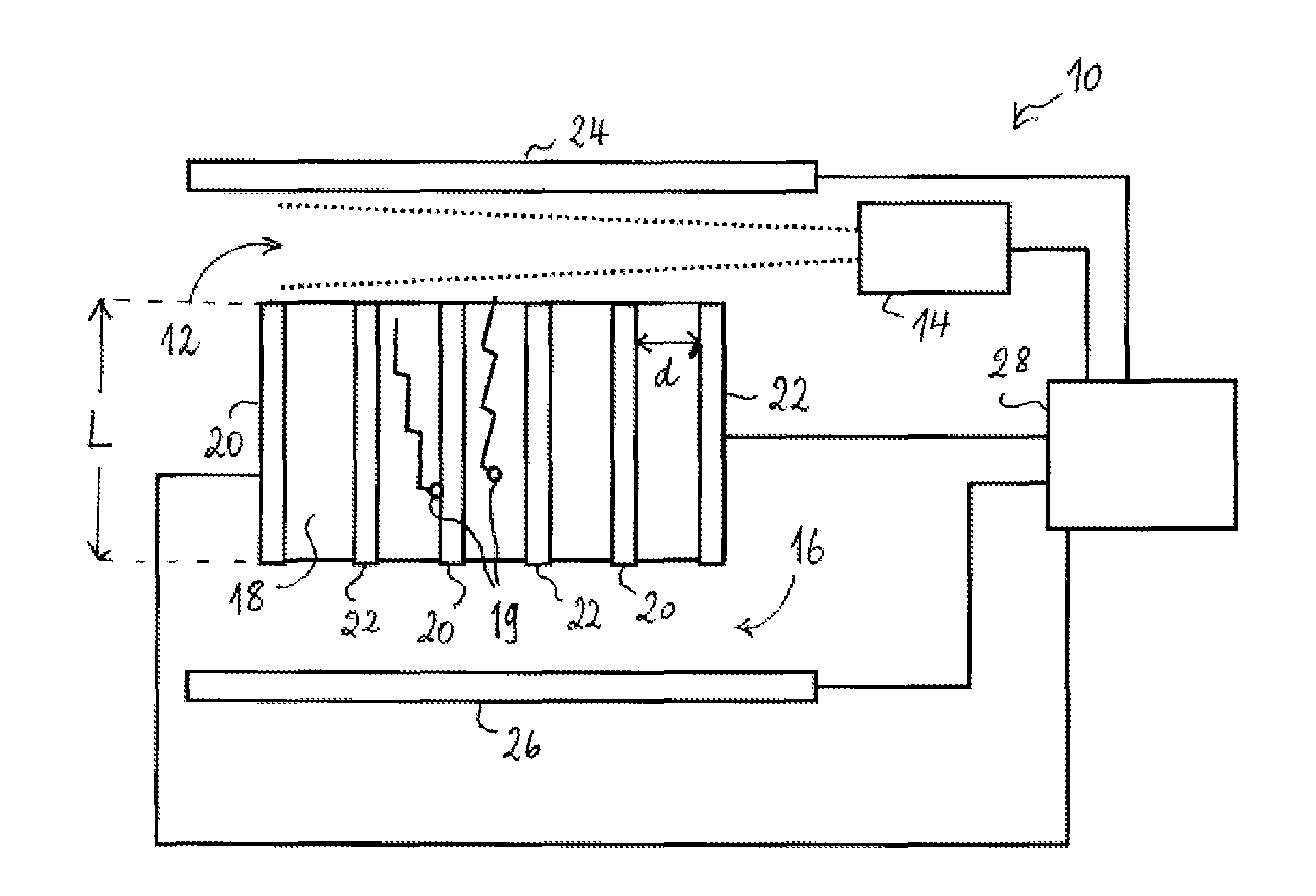
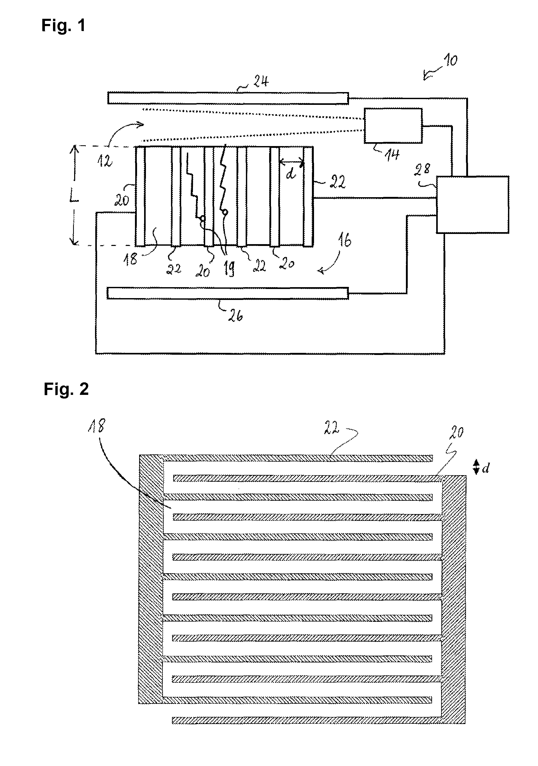
[0065]As illustrated in FIG. 1, a miniaturized differential mobility spectrometer 10 comprises an ionization chamber 12, in which analyte ions are produced from a sample to be analyzed by an ionization source 14 (such as, e.g. a UV laser). The ionization chamber 12 is in fluid connection with a detection region 16 via a filter channel 18. Two comb-shaped interdigitating electrodes 20 and 22 define the cross section of the filter channel 18, which is best shown in FIG. 2. The filter channel is disposed between two substantially planar deflection electrodes 24 and 26. When the spectrometer is in use, the different electric potentials are applied to electrodes 20, 22, 24 and 26, so as to produce an electric field in the region between them. In the electrode configuration as in FIG. 1, the separation electrodes 20 and 22 produce the transversal component of the electric field, whereas the deflection electrodes 24 and 26 produce the longitudinal component of the electric field. Other con...


PUM

PropertyMeasurementUnit
lengthaaaaaaaaaa
electric field strengthaaaaaaaaaa
concentrationaaaaaaaaaa

Abstract

A method of operating a differential mobility spectrometer includes an ionization chamber, a filter channel and a detection region. In the ionization chamber, analyte ions are produced from a sample, the so-obtained ions are then subjected in the filter channel to a time-varying electric field. The time-varying electric field has a longitudinal field component drawing the analyte ions from the ionization chamber through the filter channel into the detection region and a transversal field component, which is the superposition of an asymmetrically oscillating transversal field causing the analyte ions to move to and fro in transversal direction and a compensation field for selecting a species of analyte ions by substantially canceling the average transversal velocity of the selected species. Analyte ions of the selected species having passed through the filter channel are collected in the detection region and a detection signal responsive to the number of analyte ions collected is generated as a function of the compensating field. The longitudinal field component oscillates in longitudinal direction in such a way that it imparts to the analyte ions on average a non-zero longitudinal velocity in direction of the detection region while it causes them, on a shorter time scale, to move to and fro in longitudinal direction in the filter channel.

Description

TECHNICAL FIELD[0001]The present invention relates to devices for analysis of components of gases. More precisely, it relates to an improvement of devices known as Micro Differential Mobility Spectrometers (micro-DMS). These devices operate by ionizing the gas composition to be examined and separating the various ionized gas components by a mechanism that makes use of the different dependencies of the ion mobilities of these components upon the electric field.BACKGROUND ART[0002]Gas analysis based on field-dependent ion mobility is a powerful tool in a number of applications of a primary importance, e.g. public protection against terrorism as well as protection of military staff. This is because differential ion mobility spectrometers are capable of detecting traces of explosives and poison agents present in ambient air. Another possible application of such spectrometers is remote detection of illegal drugs.[0003]Recently, new applications of broad industrial and public interest hav...

Claims


Application Information

Patent Timeline
Patent Type & Authority Patents(United States)
IPC IPC(8): H01J49/42G01N27/62
CPCG01N27/622H01J49/42G01N27/624
Inventor BOULBITCH, ALEXEI
Owner IEE INT ELECTRONICS & ENG SA
Why Eureka
Try Eureka