
Tiller for residue crop preparation

Active Publication Date: 2014-11-18
JOHNSON MYRON Q
View PDF32 Cites 15 Cited by
  • Summary
  • Abstract
  • Description
  • Claims
  • Application Information

AI Technical Summary

Benefits of technology

The invention is a tool and technique for preparing a cover crop field for planting in a single pass. The device includes a roller or press that cuts and compresses the cover crop residue into the soil, while a shank removes debris from the planting furrow. A basket or optional furrow drum trails behind the shank to create a suitable seedbed for primary crop planting. This tool helps break down the cover crop and prepare the field for planting.

Problems solved by technology

This can save the farmer a considerable amount of time and fuel, and it reduces soil compaction due to the press weight of tractors in a field.
In reduced tillage strategies, weed suppression can be problematic, and expensive.
Hence, reduced tilling may cause an increase in total farm expenses because herbicides are used in place of cultivation for weed suppression.
For example, weeds such as Morningglory, Pigweed (including Palmer amaranth), Lambsquarters, Marestail, Waterhemp, Giant and common ragweed, Velvetleaf, Eastern Black Nightshade, and Kochia are a prevalent and increasing problem in different parts of the country.
Furthermore, even when weed seeds germinate, they often run out of stored energy for growth before building the necessary structural capacity to break through the cover crop mulch layer, thereby smothering the weed seeds before maturing into a reproducing plant.
By reducing soil erosion, cover crops often also reduce both the rate and quantity of water that drains off the field, which would normally pose environmental risks to waterways and ecosystems downstream.
Soil erosion is a process that can irreparably reduce the productive capacity of an agro-ecosystem.
The use of strip tilling with cover crops is the optimal strategy, but using an optimal strip tilling procedure can be elusive, due to the dense foliage of cover crops and due to the strong network of roots developed by cover crops.
This can require a farmer to make multiple tilling passes over a cover crop field to properly prepare the field for planting, thereby costing the farmer more in gas, time, and labor, and defeating the very purpose of strip tilling.

Method used


Image

  • Tiller for residue crop preparation
  • Tiller for residue crop preparation
  • Tiller for residue crop preparation

Examples


Embodiment Construction

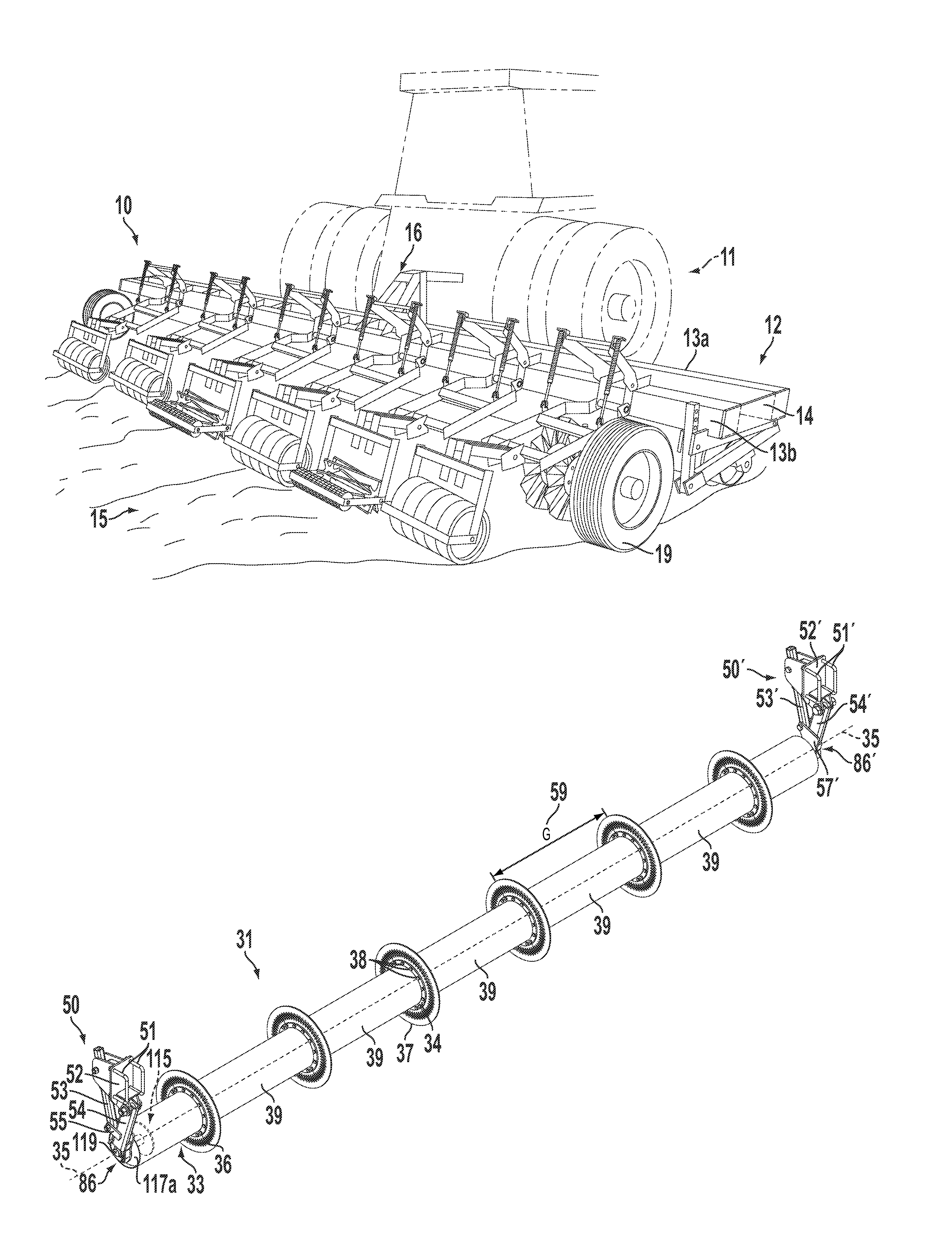
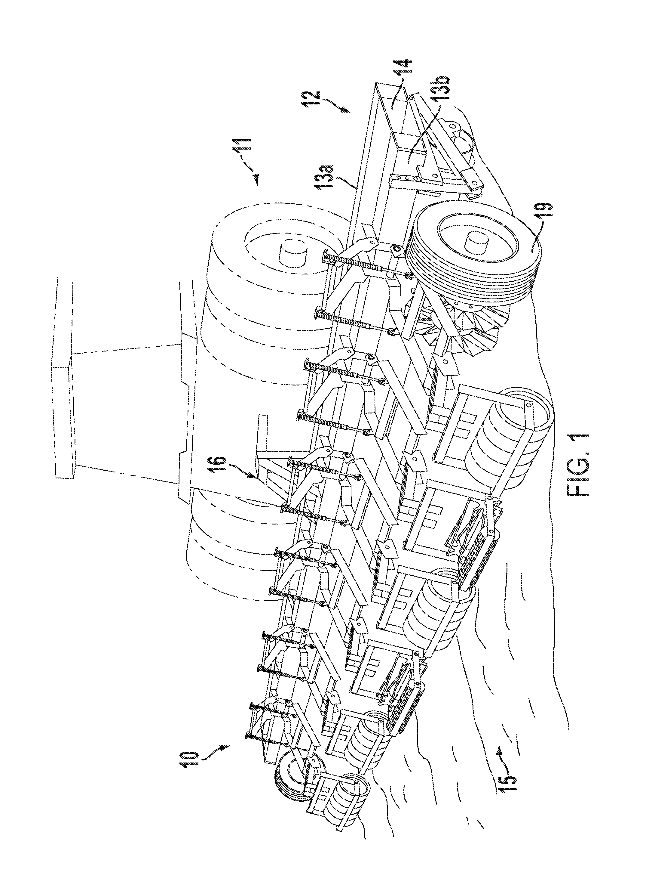
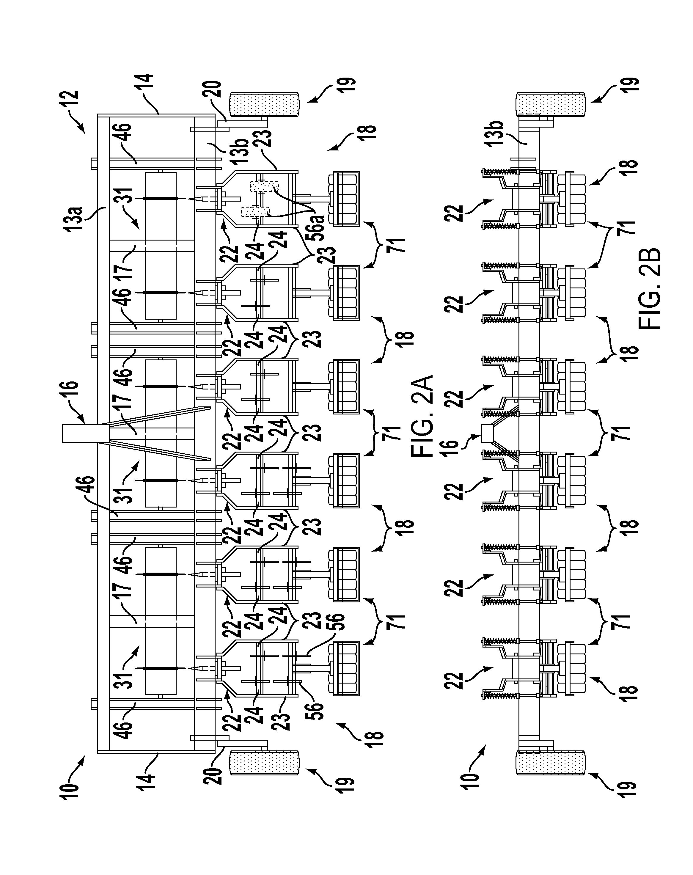
[0035]Referring to the drawings for a better understanding of the function and structure of the invention, FIG. 1 shows a perspective view of the tiller 10 when in use in a farm field. The tiller 10 is designed to be pulled by a tractor 11 to till multiple rows of soil 15 for planting seeds to grow various types of farm crops and vegetation (not illustrated). In particular, the tiller 10 is designed to till either live or killed cover crops in preparation for planting of a primary crop during the growing season. The tiller 10 is primarily a type of “strip tiller” because aside from cover crop compaction narrow strips of planting rows are tilled while leaving the surrounding compacted cover crop intact.

[0036]Pursuant to FIG. 1, a standard hitch 16 allows for the connection of the tiller 10 to tractor 11 such that hydraulic control by the tractor 11 over the tiller is maintained. The structure of the hitch 16 permits the operator of the tractor 11 to raise and lower the tiller 10 to a...


PUM


Abstract

A tilling cultivator and associated method is disclosed for strip tilling cover crop in preparation for primary crop planting. The tiller includes a pressing drum having a band coulter for cutting surface and subsurface cover crop residue roots and compressing the cover crop into the soil. A trailing shank just behind and aligned with the coulter clears debris from the planting furrow, and a pair of staggered wavy coulters behind the shank closes any shank voids. A rolling basket or other optional soil conditioners trail behind the planting furrow to create a suitable seedbed for primary crop planting. The apparatus and an associated method of use aids in cover crop decomposition and pre-plant field preparation.

Description

[0001]This application claims the benefit of filing priority under 35 U.S.C. §119 and 37 C.F.R. §1.78 of the U.S. Provisional Application Ser. No. 61 / 560,806 filed Nov. 17, 2011, for a PRE-PLANT STRIP TILLER FOR USE WITH COVER CROPS. All information disclosed in that prior provisional application is incorporated herein by referenceFIELD OF THE INVENTION[0002]The present invention relates generally to tillage farming implements trailed behind farm tractors such as field cultivators. In particular, the present invention relates to crop tillers having pressure rollers. In greater particularity, the present invention relates to tillers and cultivators that prepare crop fields having residue or cover crops planted therein just before spring planting.BACKGROUND OF THE INVENTION[0003]Reduced tillage strategies are popular in farming. Reduced tillage techniques include no tilling, strip tilling, mulch tilling, rotational tilling, and ridge tilling. Of these tillage techniques, strip tilling...

Claims


Application Information

Patent Timeline
IPC IPC(8): A01B49/02
CPCA01B49/027A01B33/024
Inventor JOHNSON, MYRON QUINTONSANDERS, JR., JOHN W.
Owner JOHNSON MYRON Q
Learn More