Modular RF connector system
a connector system and module technology, applied in the direction of coupling contact members, coupling device connections, coupling protective earth/shielding arrangements, etc., can solve the problems of limited expansion of the space available for electrical connectors, and inability to increase the density of electrical connectors, etc., to achieve the effect of increasing the port density of connectors
- Summary
- Abstract
- Description
- Claims
- Application Information
AI Technical Summary
Benefits of technology
Problems solved by technology
Method used
Image
Examples
first embodiment
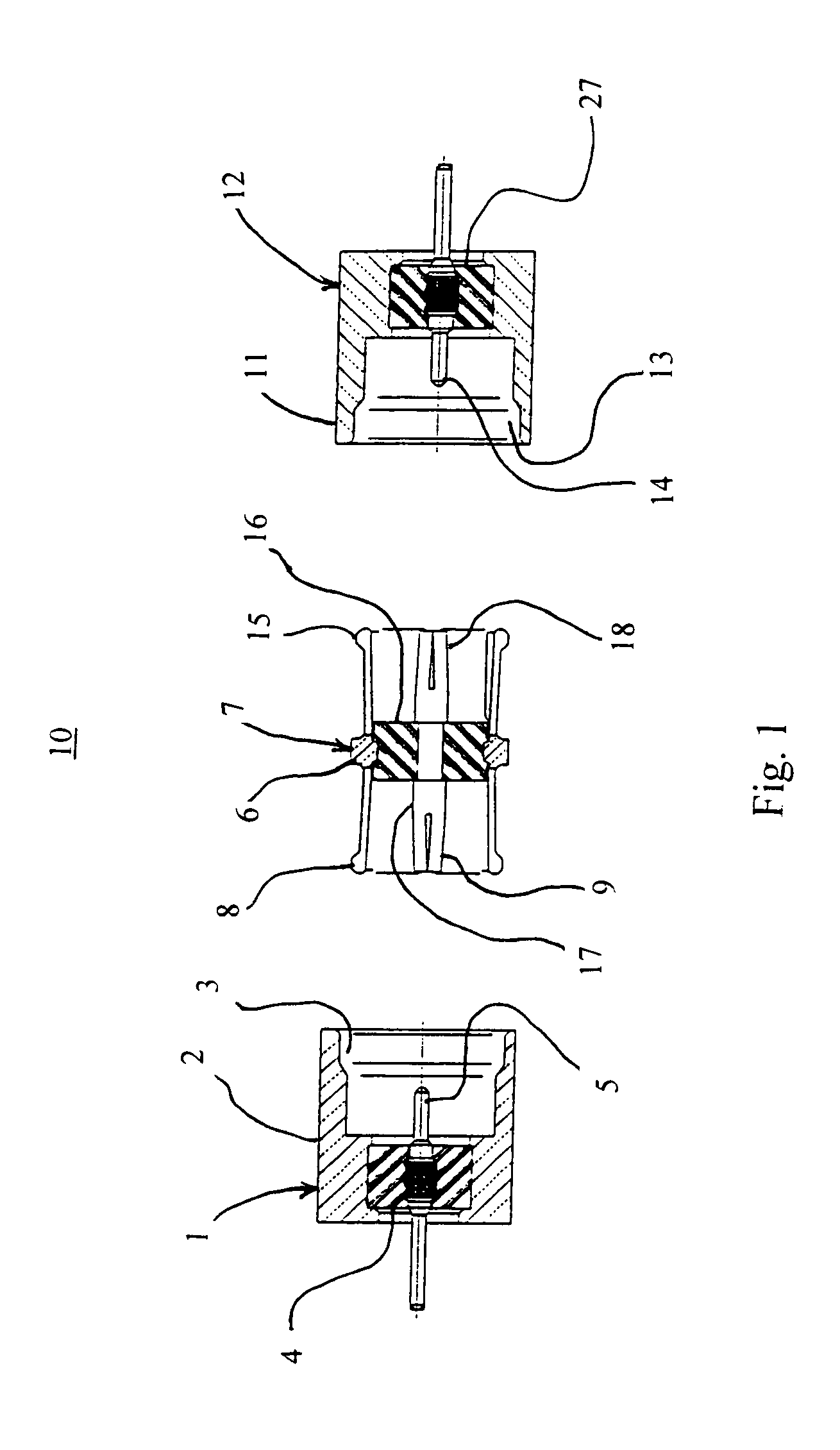
[0036]FIG. 1 is a cross-sectional side view of the electrical connector of the invention. The connector assembly 10 is a 75 Ohm SMP style connector which includes a first connector 1, an adaptor 7, and a second connector 12. The first connector 1 includes an electrically conductive outer conductor 2, a layer of insulation material 4, and a center contact 5 which is electrically conductive. The layer of insulation material 4 retains the center contact 5, and the layer of insulation material is retained by the outer conductor 2. The outer conductor 2 forms a recess 3. The center contact 5 is electrically isolated from the outer conductor 2 by the layer of insulation material 4. The center contact 5 is a male contact.
[0037]The second connector 12 of FIG. 1 is similar to the first connector 1. The second connector 12 includes an electrically conductive outer conductor 11, a layer of insulation material 27, and a center contact 14. The outer conductor 11 forms a recess 13.
[0038]The adapt...
second embodiment
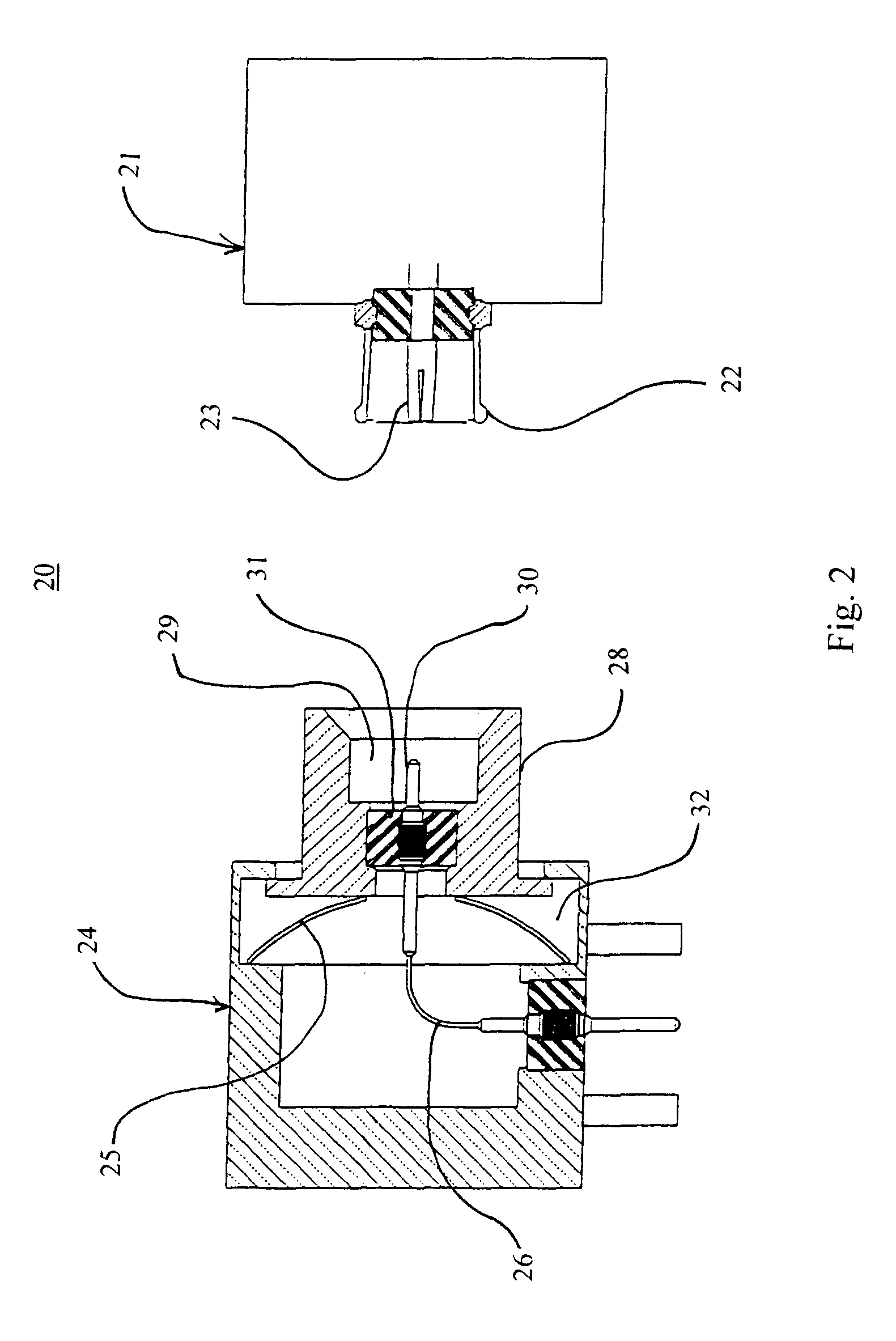
[0040]FIG. 2 is a cross-sectional side view of the electrical connector of the invention. The connector assembly 20 includes a floating nose style 75 Ohm SMP style connector 24 which is mateable to connector 21. The floating nose connector 24 includes an outer conductor 28, a layer of insulation material 31, and a center contact 30. The center contact 30 is attached to a flexible wire 26. The center contact 30 is in electrical communication with the flexible wire 26. The outer conductor 28 includes a recess 29 so as to accommodate an outer conductor 22 of the connector 21. The outer conductor 28 is in contact with a spring washer 25. The spring washer 25 is retained within a recess 32 of the connector 24. The outer conductors 28, 22, the center contacts 30, 23, and the layers of insulation material 31 are made of suitable engineering materials.
[0041]In use, when the connector 21 is mated to the connector 24, the two connectors 21, 24 may be somewhat misaligned relative to each other...
third embodiment
[0042]FIG. 3 is a cross-sectional side view of the electrical connector of the invention. The connector assembly 40 includes a first connector 41, an adaptor 47, and a second connector 53. The first connector 41 includes an outer conductor 42, a layer of insulation, and a center contact 44. The outer conductor 42 includes a recess 43. The outer conductor 42 includes an inner annular projection 45 in the recess 43. The inner annular projection 45 is retained by the outer conductor 42. The outer conductor 42 and the inner annular projection 45 are in electrical communication. The layer of insulation material 46 is retained between the inner annular projection 45 and the center contact 44. The center contact 44 is not in electrical communication with the outer conductor 42 including the inner annular projection 45.
[0043]The second connector 53 of FIG. 3 includes an outer conductor 54, a layer of insulation material 57, and a center contact 56. The outer conductor 54 forms a recess 55. ...
PUM
 Abstract
Description
Claims
Application Information
 - R&D
- Intellectual Property
- Life Sciences
- Materials
- Tech Scout
- Unparalleled Data Quality
- Higher Quality Content
- 60% Fewer Hallucinations
Browse by: Latest US Patents, China's latest patents, Technical Efficacy Thesaurus, Application Domain, Technology Topic, Popular Technical Reports.
© 2025 PatSnap. All rights reserved.Legal|Privacy policy|Modern Slavery Act Transparency Statement|Sitemap|About US| Contact US: help@patsnap.com


