Separating device for removing sand and rock particles

a separation device and rock technology, applied in the direction of drinking water installation, borehole/well accessories, construction, etc., can solve the problems of low fracture toughness, low wear resistance, and great wear resistan

Active Publication Date: 2014-11-25
3M INNOVATIVE PROPERTIES CO
View PDF41 Cites 20 Cited by
  • Summary
  • Abstract
  • Description
  • Claims
  • Application Information

AI Technical Summary

Benefits of technology

[0015]A further advantage of the separating devices according to the invention is that the use of solid, brittle-hard materials, in particular ceramic materials, brings about the advantages of abrasion and corrosion resistance. The expression “solid” means in connection with the materials according to the invention that, by contrast with the solutions of the prior art, they are not porous, so that the materials used according to the invention themselves do not exhibit any filtering effect. The abrasion and wear resistance and the corrosion resistance of the separating devices according to the invention are consequently much greater than in the case of the devices of the prior art described.
[0017]A further advantage of the separating devices according to the invention is that rapid clogging of the free screen areas does not occur. It is therefore not necessary to flush the separating devices according to the invention clear at frequent intervals, as in the case of the solutions known in the aforementioned prior art. It is therefore sufficient to flush the separating devices according to the invention clear at greater time intervals, if required.
[0019]Furthermore, the separating devices according to the invention can be introduced into curved wells, which represents a further advantage over the systems described in US 2004 / 005 0217 A1 and WO 2008 / 080402 A1.

Problems solved by technology

A major disadvantage of this type of construction is its low resistance to wear.
The abrasive rock particles cause great wear.
One problem of the solutions described in these two documents is that, on account of their low fracture toughnesses, filters of porous ceramic materials tend to fracture as a result of flexural loading.
The ultimate bending strength is generally well below 30% of that of the corresponding solid material and is therefore not sufficient for the mechanical loads under the operating conditions in wells drilled in rock.
A further problem is that the abrasion resistance of porous ceramic materials is much less than that of solid ceramic materials.
Furthermore, the solutions described in US 2004 / 005 0217 A1 and WO 2008 / 080402 A1 are disadvantageous in that very rapid clogging of the free screen area occurs.

Method used


Image

  • Separating device for removing sand and rock particles
  • Separating device for removing sand and rock particles
  • Separating device for removing sand and rock particles

Examples


example 1

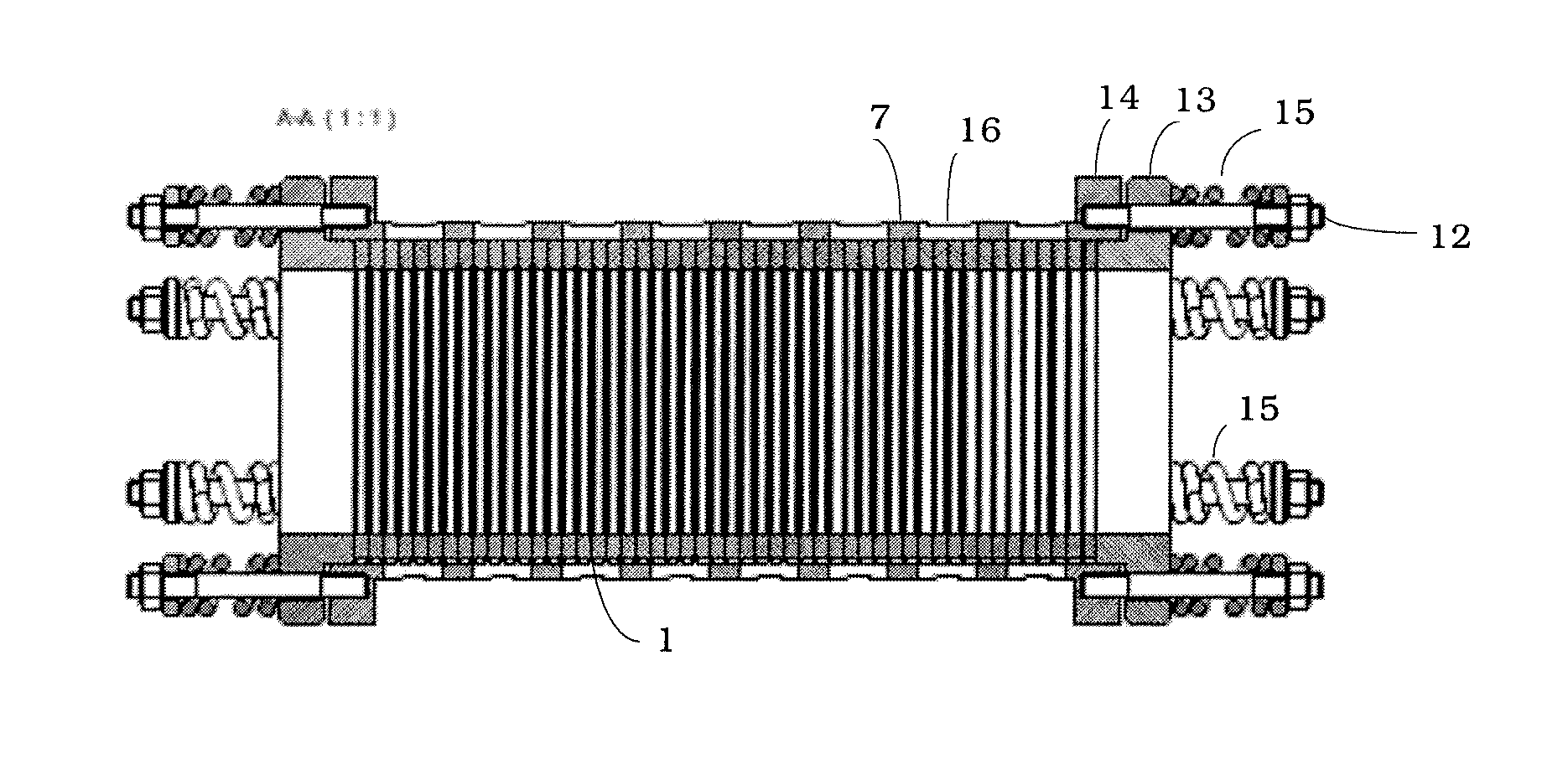
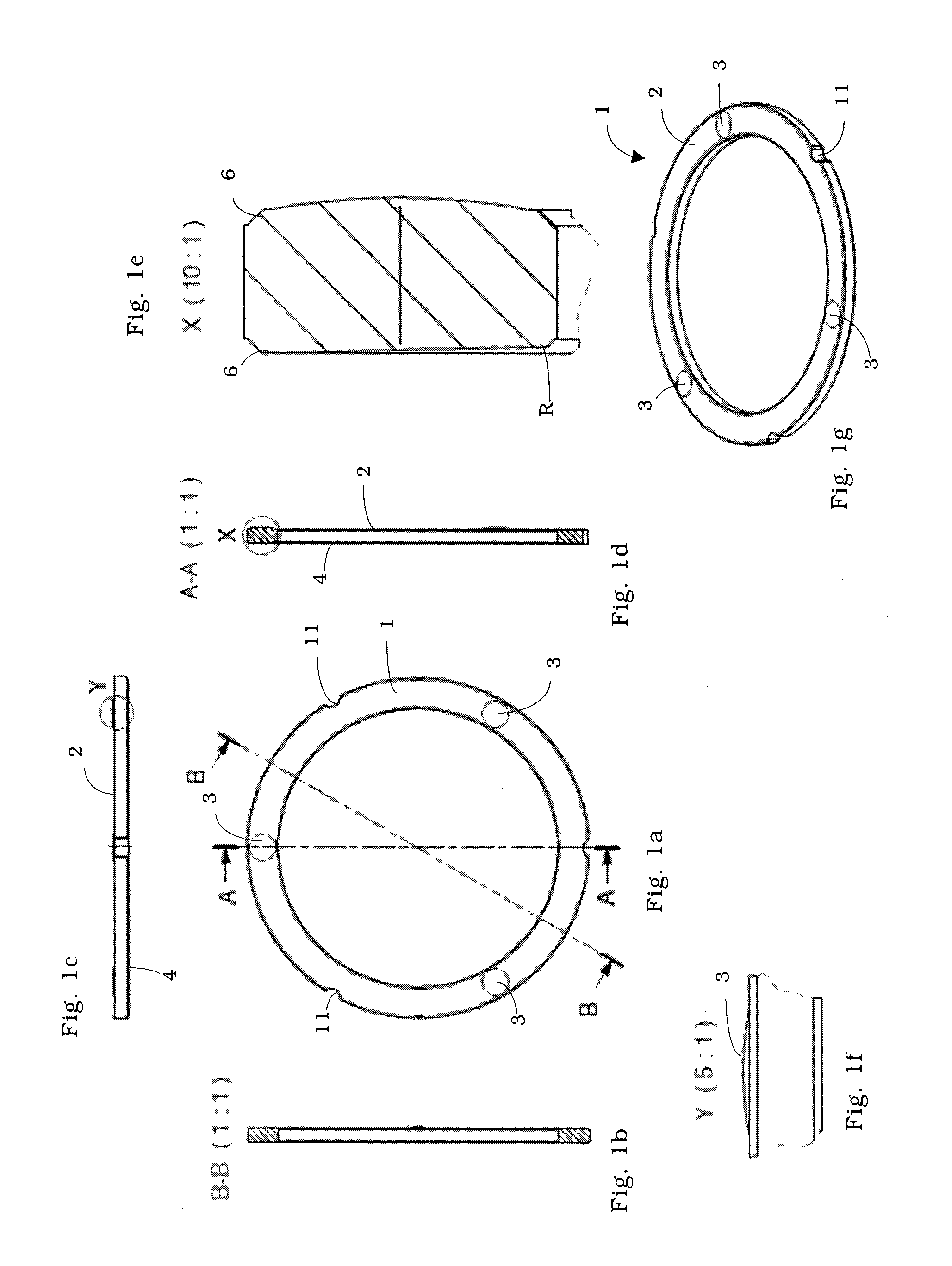
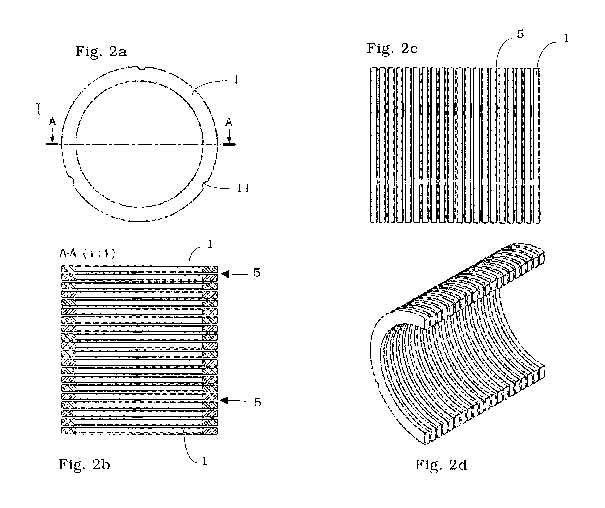
Ceramic Separating Device

[0069]In a design example, the outside diameter of the annular filter discs is 100 mm, the inside diameter 80 mm. The height of the annular discs is 3 mm. The radius R of the spherical axial bearing (see FIG. 1e) is 2000 mm. The annular gap between two neighbouring annular discs is in each case 0.4 mm. The radius of the three spacers, in the form of spherical portions, on the annular discs is 25 mm. The wall thickness of the metal supporting cage is 3 mm (see FIGS. 3b and 3c). The free filter area is 13%.

[0070]The total length of the separating device in the example is 1000 mm; this corresponds to 294 discs with the aforementioned dimensions in the disc stack.

[0071]In the exemplary embodiment, the material SSiC (EKasic® F) is used.


PUM


Abstract

Provided herein is a separating device for removing sand and rock particles in the extraction of liquids or gases from wells drilled in rock having a plurality of brittle-hard annular discs stacked one on top of another and axially braced by a supporting structure. The annular discs have at least three spacers uniformly distributed over the circumference on their upper side. The discs are stacked on each other such that the spacers lie one over another and a separating gap with a height of 0.05-1 mm, preferably 0.2-0.5 mm, is present between each of the discs. Similarly, another embodiment of the separating device has a plurality of brittle-hard bush-shaped elements with slits formed therein.

Description

[0001]This is a National Phase Application filed under 35 U.S.C. §371 as a national stage of PCT / EP2009 / 008021, filed on Nov. 10, 2009, an application claiming the benefit under 35 U.S.C. §119 of German Patent Application No. 10 2008 057 894.0, filed on Nov. 18, 2008, the content of each of which is hereby incorporated by reference in its entirety.FIELD OF THE INVENTION[0002]The invention relates to novel separating devices with the aid of which sand and rock particles can be removed in a process for the extraction of liquids or gases from wells drilled in rock, and consequently the liquids or gases can be extracted effectively.BACKGROUND OF THE INVENTION[0003]In the extraction of liquids and gases from wells drilled in rock, there is in principle the problem of flushing out fine sand and rock particles that have to be separated already in the well from the medium that is to be extracted. This problem occurs in particular in the extraction of mineral oil and natural gas, but also in...

Claims


Application Information

Patent Timeline
Patent Type & Authority Patents(United States)
IPC IPC(8): E21B43/08
CPCE21B43/086
Inventor KAYSER, ARMIN
Owner 3M INNOVATIVE PROPERTIES CO
Why Eureka
Try Eureka