Surface-coated member

a surface coating and member technology, applied in the field of surface coating members, can solve the problems of affecting the cutting speed of the cutting tool, and the rake surface or peeling of the hard coating layer, etc., and achieves the effects of high feed rate cutting, excellent breakage resistance, and high wear resistan

Active Publication Date: 2007-02-06
KYOCERA CORP
View PDF8 Cites 18 Cited by
  • Summary
  • Abstract
  • Description
  • Claims
  • Application Information

AI Technical Summary

Benefits of technology

[0019]An advantage of the present invention is to provide a surface-coated member such as a surface-coated cutting tool of long service life that shows excellent breakage resistance and high wear resistance without chipping or peel-off in interface between the base body, TiCN layer and Al2O3 layer under harsh cutting conditions such as high-speed cutting and high feed rate cutting, or in cutting operations that require particularly wear resistance.
[0020]The inventor of the present application continued researches on the method to improve breakage resistance without compromising the wear resistance of a surface-coated member that comprises a base body and a hard coating layer consisting of the TiCN layer and the Al2O3 layer formed in this order on the surface of the base body. Through these researches, it was found that adhesion force between the base body, the TiCN layer and the Al2O3 layer can be improved by forming the TiCN layer from stringer-like TiCN crystal that is grown in a direction perpendicular to the base body and controlling the mean crystal width of the TiCN layer on the Al2O3 layer side larger than the mean crystal width on the base body side.
[0021]With this constitution, a surface-coated member that shows excellent wear resistance and high breakage resistance is obtained since strong bonding of the hard coating layer can be maintained even when the Al2O3 layer is formed with a large thickness that is required for improving the wear resistance, while occurrence of chipping and peel-off of layers near the interface between the base body, the Al2O3 layer and the TiCN layer can be avoided even in cutting operations under harsh cutting conditions where the cutting edge of the cutting tool is subject to strong impact, including heavy intermittent cutting of metal such as cast iron that contains high-hardness graphite grains scattered therein including, in particular, gray cast iron (FC) or ductile cast iron (FCD).
[0022]The surface-coated member of the present invention is constituted as described in (1a) through (1c).
[0023](1a) The member comprises a base body comprising cemented carbide and a hard coating layer comprising at least an Al2O3 layer and a TiCN layer formed in this order on the surface of the base body.
[0024](1b) The TiCN layer is formed from stringer-like TiCN crystal that is grown in a direction perpendicular to the base body.

Problems solved by technology

As high efficiency cutting operations become commonplace, conventional cutting tools experience such problems as the hard coating layer cannot endure strong impact generated in cutting operations where the cutting edge receives strong impact such as heavy intermittent cutting of metal, eventually resulting in chipping of the rake surface or peel-off of the hard coating layer.
Thus service life of the cutting tool is limited by sudden occurrence of tool breakage such as breakage or abnormal wear of the cutting edge.
However, the constitution disclosed in Japanese Patent No. 3230372 cannot solve the problem that the hard coating layer is liable to peel-off near the interface between the Al2O3 layer and the TiCN layer.
Thus cutting operations where the cutting edge receives strong impact such as heavy intermittent cutting of metal have still been prone to chipping and / or peel-off of the hard coating layer in the interface between the Al2O3 layer and the TiCN layer.
In case thickness of the hard coating layer is decreased for the purpose of preventing chipping and peel-off of the hard coating layer, the hard coating layer disappears prematurely, resulting in accelerated wear and failure to extend tool life of the cutting tool.
In case attention is directed only to the adhesion force between the Al2O3 layer and the TiCN layer, adhesion force between the TiCN layer and the base body is compromised, thus leading to peel-off from the TiCN layer and failure to elongate the service life of the cutting tool.
However, in case castings such as gray cast iron (FC) or ductile cast iron (FCD), or steel having inhomogeneity in hardness or unusual shape is cut, sporadic application of strong impact to the cutting edge of the tool causes the coating layer including the TiCN layer to peel off, thus exposing the base body and rapid progress of wear.
Moreover, when thickness of the layer involves variability among individual tools, thinner Al2O3 layer leads to plastic deformation due to lower wear resistance.
Thicker Al2O3 layer, on the other hand, causes the coating layer including the TiCN layer to peel off, thus exposing the base body and resulting in rapid progress of wear.
With the constitution described in Japanese Patent No. 3269305, however, the cutting edge is still subject to abnormal wear due to chipping, thus resulting in short service life of the cutting tool under harsh cutting conditions which are often employed recently such as heavy intermittent cutting where the cutting edge is subject to sudden application of strong impact.
In case thickness of the hard coating layer is decreased for the purpose of preventing chipping and or peel-off of the hard coating layer, the hard coating layer disappears prematurely, resulting in accelerated wear and failure to elongate the service life of the cutting tool.
However, titanium oxide cannot endure the high-load machining operations which are dominant recently.
According to Japanese Unexamined Patent Publication No. 10-109206, however, although the tool damage by membrane separation can be prevented, the breakage-proof nature and wear resistances of a hard covering layer itself are insufficient, and the enough tool life cannot be acquired.

Method used


Image

  • Surface-coated member
  • Surface-coated member
  • Surface-coated member

Examples


embodiment 1

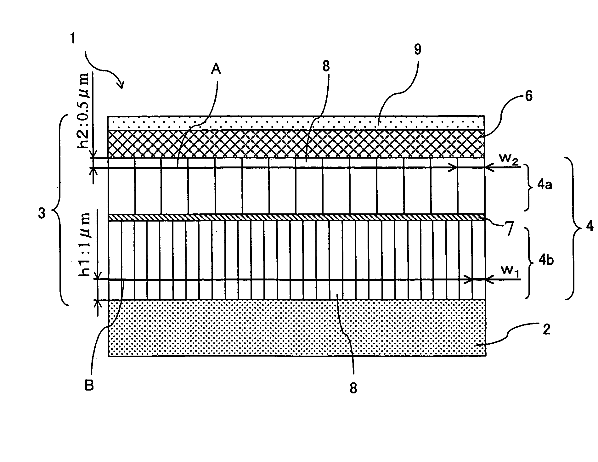
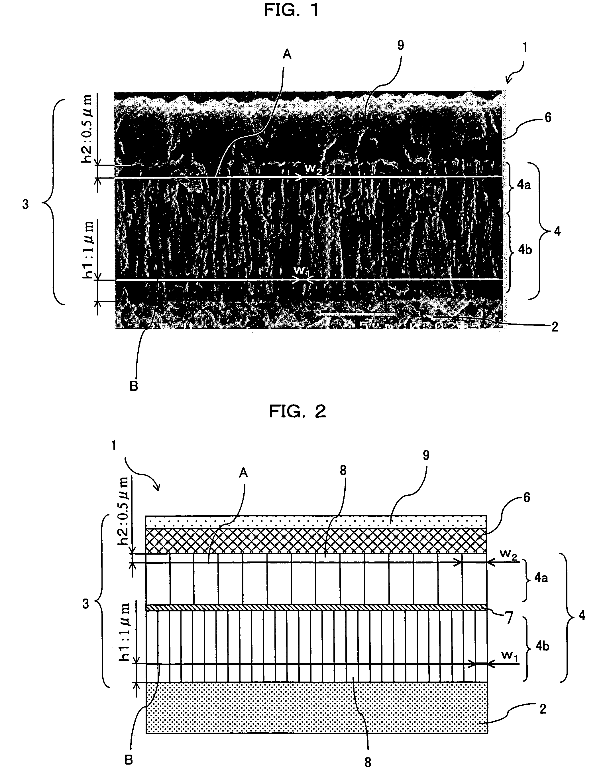
[0052]An example of the cutting tool which is a preferred embodiment of the surface-coated member of the present invention will be described below with reference to FIG. 1 which is a photograph taken with a scanning electron microscope (SEM) showing a fracture surface including the hard coating layer and FIG. 2 which schematically shows the same.

[0053]In FIG. 1, the surface-coated cutting tool (hereinafter referred to simply as the cutting tool) 1 comprises a base body 2 and a hard coating layer 3 formed thereon. The base body 2 may be made of, for example, (i) cemented carbide consisting of carbonitride phase made of tungsten carbide (WC) and at least one kind selected from among a group of carbide, nitride and carbonitride of metals of the groups 4a, 5a and 6a of the Periodic Table that is held together by a binder phase consisting of an iron group metal such as cobalt (Co) and / or nickel (Ni); or (ii) a hard alloy such as cermet consisting mainly of titanium carbide (TiC) or titan...

embodiment 2

[0079]This embodiment is to obtain the cutting tool 1 by coating the surface of the base body 2 with the hard coating layer 3 similarly to the above embodiment. The hard coating layer 3 consists of at least the titanium carbonitride (TiCN) layer and the alumina (Al2O3) layer formed successively on the surface of the base body 2, while the TiCN layer is formed from stringer-like TiCN crystal that is grown in a direction perpendicular to the interface with the base body and is constituted from at least two layers having different ratios C / N of proportions of carbon C and nitrogen N, namely a carbon-rich TiCN layer where C / N ratio is in a range of 1.5≦C / N≦4 located at the top on the Al2O3 layer 3 side, and a nitrogen-rich TiCN layer located below the carbon-rich TiCN layer where the ratio C / N is in a range of 0.2≦C / N≦0.7.

[0080]The ratio C / N of carbon C and nitrogen N in the TiCN layer is measured on a fracture surface of the coating film or a surface obtained by polishing the fracture ...

embodiment 3

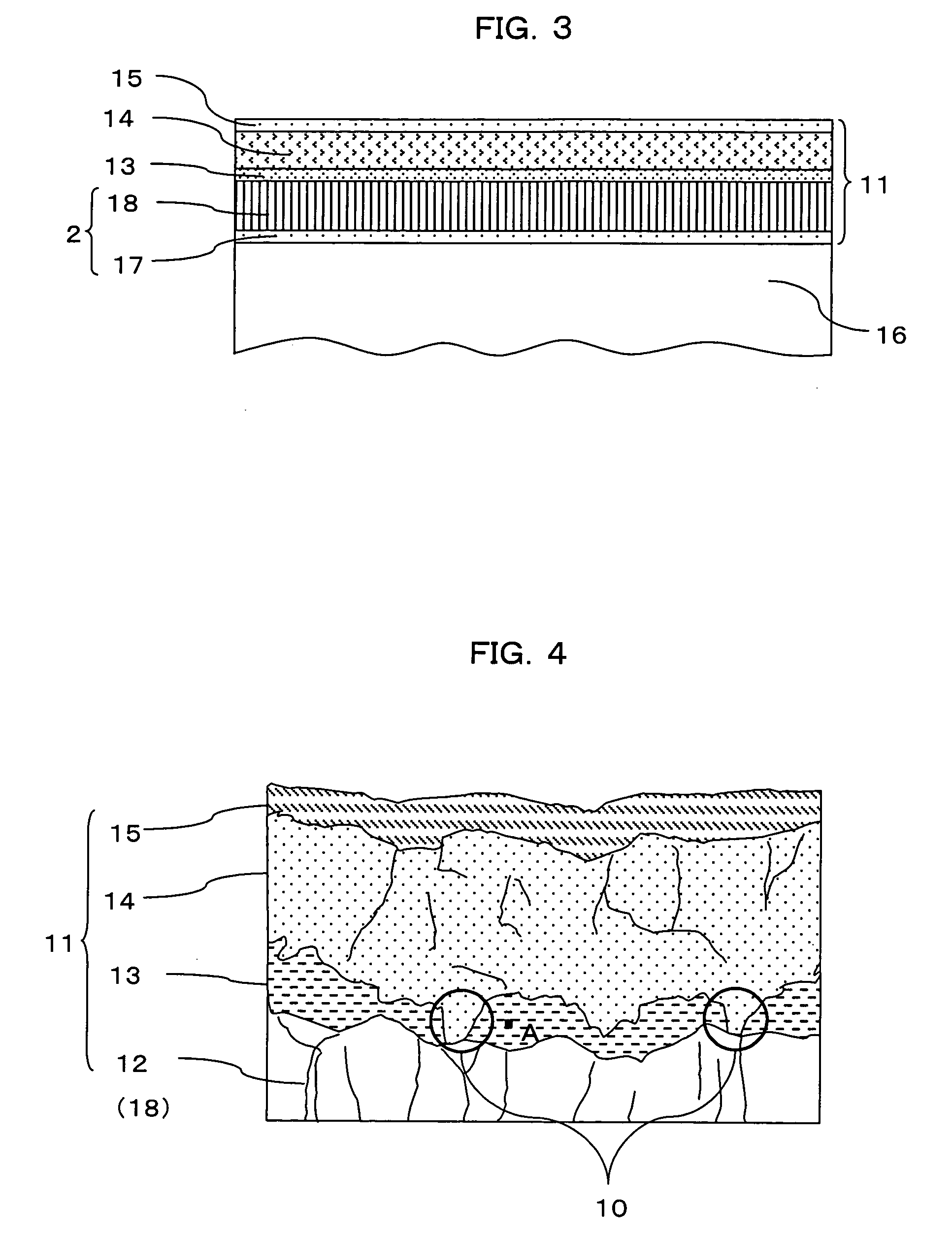
[0096]The cutting tool of this embodiment will be described below with reference to FIG. 3 through FIG. 6. In FIG. 3, the cutting tool of the present invention comprises a base body 16 made of tungsten carbide-based cemented carbide and a hard coating film 11 formed so as to coat the surface of the base body by successively forming a Ti-based layer (first layer) containing the TiCN layer 12 mentioned above and an Al2O3 layer 14 (third layer).

[0097]A binding layer 13 (second layer) that includes at least titanium (Ti), aluminum (Al), tungsten (W) and cobalt (Co) is interposed between the Ti-based layer containing the TiCN layer 12 and the Al2O3 layer 14. The binding layer 13 serves the role of the intermediate layer to increase the adhesion force between the TiCN layer 12 and the Al2O3 layer 14, increase the adhesion force of the hard coating layer 1 and suppress the cutting performance such as chipping resistance, film peel-off resistance and wear resistance from decreasing during c...


PUM

PropertyMeasurementUnit
crystal widthaaaaaaaaaa
thicknessaaaaaaaaaa
adhesion forceaaaaaaaaaa

Abstract

The surface-coated member 1 is constituted by coating the surface of the base body 2, made of such a material as cemented carbide or cermet, with the hard coating layer 3 that comprises at least one TiCN layer 4 and the Al2O3 layer 6 formed on the surface of the TiCN layer 4, wherein the TiCN layer 4 is constituted from stringer-like TiCN crystal grown in a direction perpendicular to the base body 2 and mean crystal width w1 of the TiCN layer 4 on the Al2O3 layer 6 side is made larger than mean crystal width w2 on the base body 2 side. This surface-coated member, as a cutting tool, shows excellent breakage resistance and high wear resistance with a long service life, where strong adhesion force of the hard coating layer can be maintained without experiencing peel-off between the TiCN layer and the Al2O3 layer even in cutting operations under harsh cutting conditions, such as intermittent cutting operation where the cutting edge is subject to strong impact.

Description

[0001]Priority is claimed to Japanese Patent Application No. 2003-37556, filed on Feb. 17, 2003, No. 2003-86066, filed on Mar. 26, 2003, No. 2003-336315, filed on Sep. 26, 2003, No. 2003-397311, filed on Nov. 27, 2003, No. 2003-431557, filed on Dec. 25, 2003, No. 2004-22289, filed on Jan. 29, 2004, and No. 2004-22290, filed on Jan. 29, 2004, the disclosure of which is incorporated by reference in its entirety.BACKGROUND OF THE INVENTION[0002]1. Field of the Invention[0003]The present invention relates to a surface-coated member such as a surface-coated cutting tool that is coated with a hard coating layer having excellent chipping resistance and high wear resistance, and particularly to a surface-coated cutting tool that shows high breakage (fracture) resistance and high cutting performance under harsh cutting conditions.[0004]2. Description of Related Art[0005]A common type of cutting tool used widely in metal cutting operations is the surface-coated cutting tool that comprises a b...

Claims


Application Information

Patent Timeline
Patent Type & Authority Patents(United States)
IPC IPC(8): B23B27/00C23C30/00
CPCC23C30/005Y10T428/252Y10T428/24975
Inventor FUKANO, TSUYOSHIUSAMI, KEIJIISHII, HIROKITANIBUCHI, TAKAHITO
Owner KYOCERA CORP
Why Eureka
Try Eureka