Bearing device

a bearing and ring technology, applied in the direction of bearings, shafts and bearings, rotary bearings, etc., can solve the problems of abnormal wear, abrasion, seizure, and difficulty in obtaining the desired seizure load

Inactive Publication Date: 2006-01-31
KOMATSU LTD
View PDF8 Cites 18 Cited by
  • Summary
  • Abstract
  • Description
  • Claims
  • Application Information

AI Technical Summary

Benefits of technology

[0023]According to this structure, the sliding surfaces between the bearing and the shaft member can slide under an appropriate contact pressure. It becomes unnecessary to set larger the inner diameter of the bearing, the diameter of the shaft member and a length thereof in its axial direction, the bearing device itself is prevented from being increased in size, and the above-described effects are reliably exhibited.
[0024]In the present invention, it is preferable that a surface of either one of the bearing and the shaft member is subjected to induction hardening. According to this structure, single or multi races which are parallel to one another can be formed as the oil-supply groove portions inexpensively.

Problems solved by technology

If the area ratio is smaller than 30%, it is difficult to obtain a desired seizure load, and if the area ratio exceeds 90%, load resistance of the sliding surfaces of the bearing and the shaft member cannot sufficiently be obtained.
As a result, abnormal wear, abrasion, seizure and the like are increased, or the damage is prone to be generated, and a long lifetime of the bearing device under a rigorous using condition cannot be obtained.

Method used


Image

  • Bearing device
  • Bearing device
  • Bearing device

Examples


first embodiment

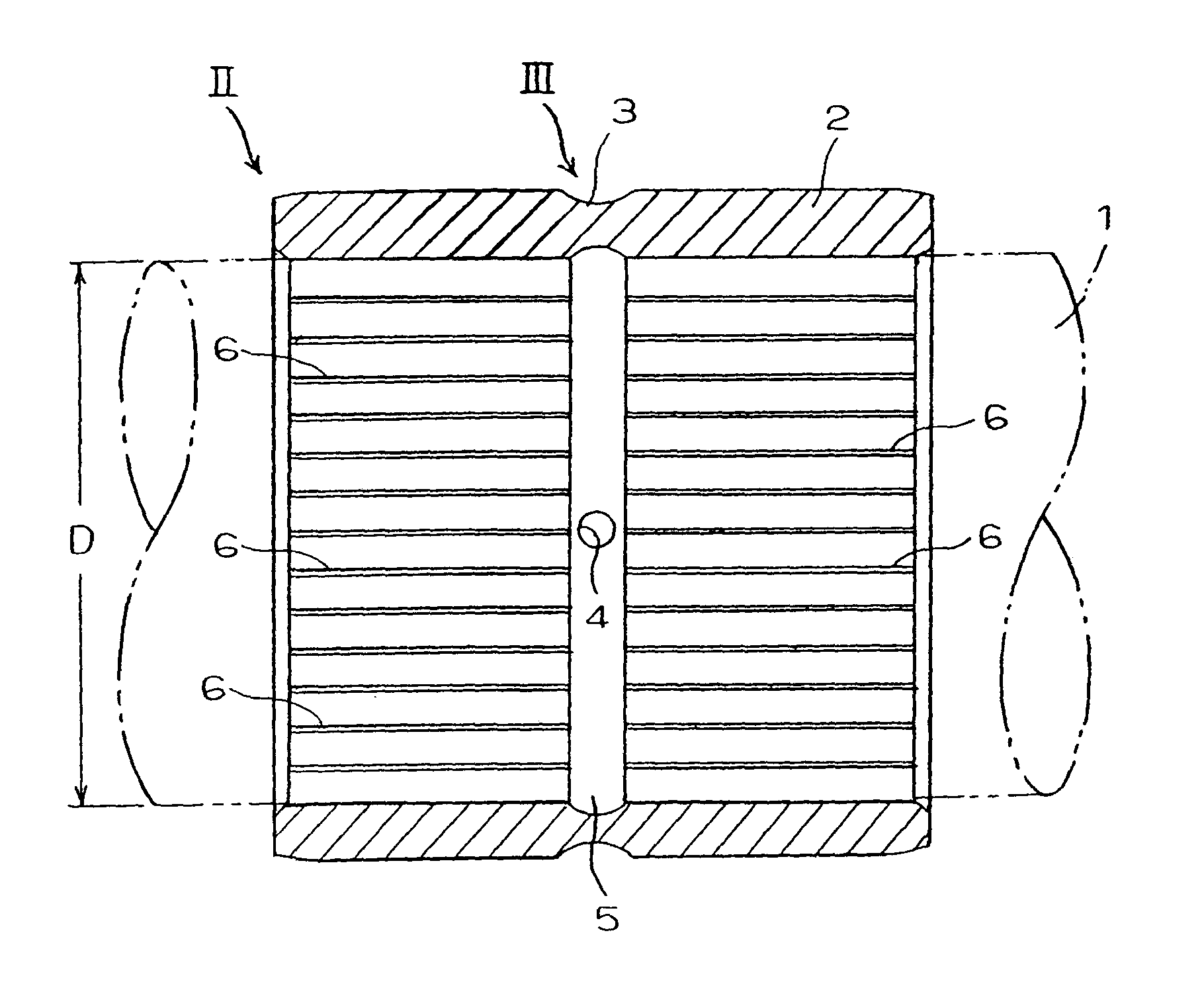
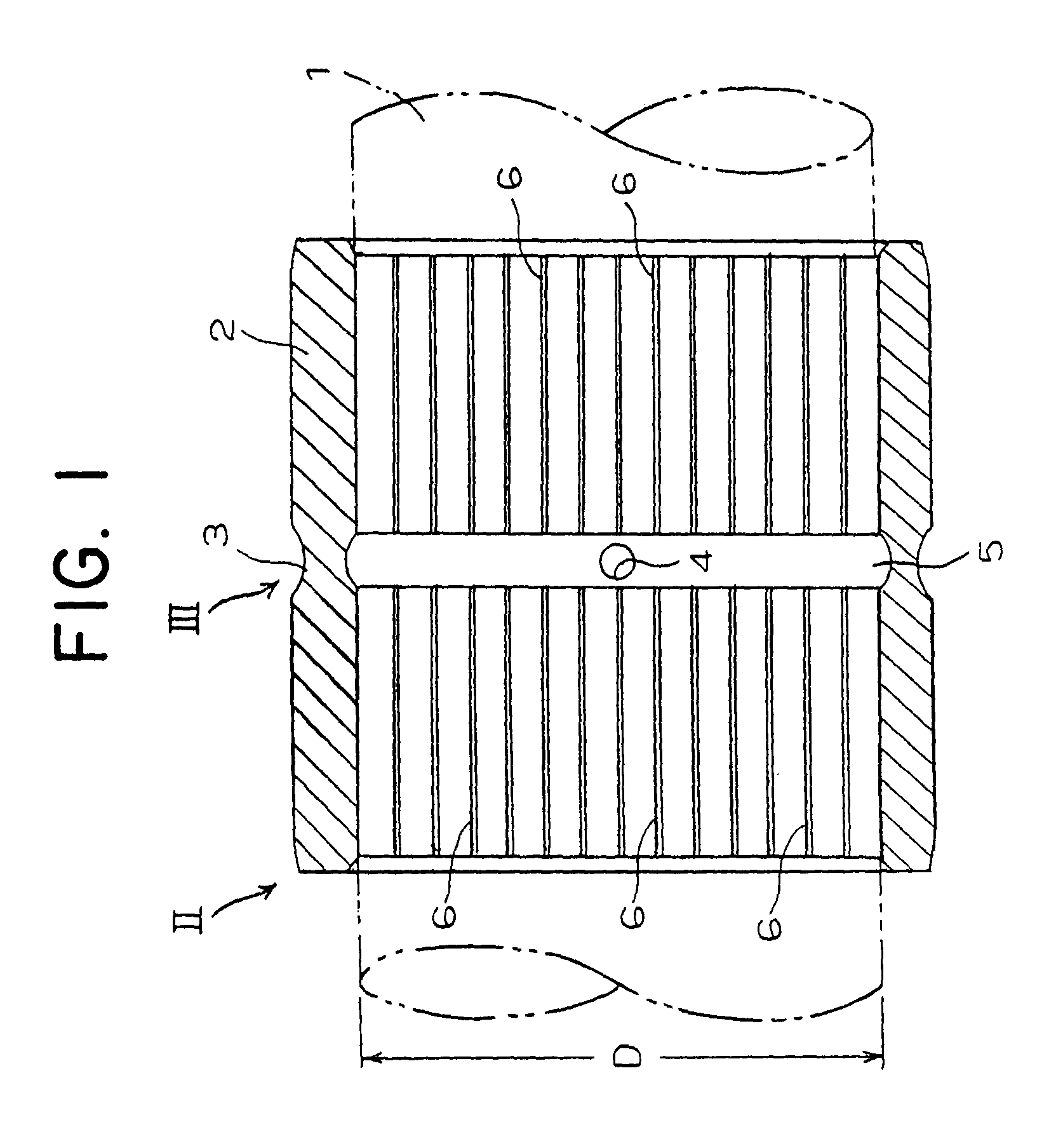
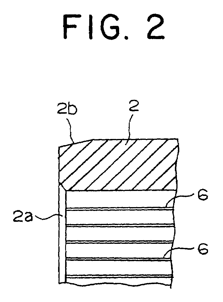
[0035]FIGS. 1 to 5 schematically show a structure of a bearing constituting a portion of a bearing device according to a representative first embodiment of the present invention. FIG. 1 is a schematic sectional view of the bearing. FIG. 2 is an enlarged view showing an end portion of the bearing at an arrow II in FIG. 1. FIG. 3 is an enlarged view showing a peripheral portion of the bearing at an arrow III in FIG. 1. FIG. 4 is an enlarged view showing an oil-supply groove portion of the bearing. FIG. 5 is an enlarged sectional view of the oil-supply groove portion taken along a line IV—IV in FIG. 4.

[0036]In these drawings, the bearing device is applied to the connection part of the utility machine which connects an arm and a bucket mounted to an excavator (not shown). The bearing device includes a journal shaft 1 as a shaft member. The journal shaft 1 is fixed and supported between a pair of brackets of the bucket (not shown). A cylindrical boss (not shown) is rotatably fitted over ...

second embodiment

[0051]FIGS. 6 and 7 show a bearing which is a partial constituting member of the bearing device of the invention. FIG. 6 is a vertical sectional view of the bearing, and FIG. 7 is an enlarged view showing oil-supply groove portions of the bearing.

[0052]A structure of the second embodiment is basically the same as that of the bearing device of the first embodiment except that the inner peripheral surface of the bush 2 which is a bearing is formed with second oil-supply groove portions 6 which are inclined at a predetermined angle α. Therefore, in FIGS. 6 and 7, substantially the same members as those in the first embodiment are designated with the same names and numerals, and detailed explanation of these members is omitted.

[0053]In FIGS. 6 and 7, the second oil-supply groove portions 6 which are inclined with respect to the axial direction of the bush at the predetermined inclination angle α are helically formed on the inner peripheral surface of the bush 2, and a plurality of the s...

experiment example 1

[0061

[0062]As machining conditions by a conventional NC lathe, or by a broaching machine, or kurling machining conditions by a lathe, machining intervals of the grooves were set to three values, i.e. 10° (6.1 mm, groove area ratio of 8%), 5° (3.05 mm, groove area ratio of 16%) and 2.5° (1.53 mm, groove area ratio of 32%). A plurality of arc groove portions each having a width of 0.5 mm and a depth of 0.2 mm were formed on an inner peripheral surface of a cylindrical bush 2 having an inner diameter of a cylindrical portion of 70 mm, an outer diameter of the cylindrical portion of 85 mm and a length of the cylindrical portion of 85 mm in parallel to the axial direction of the bush. These bushes 2 were subjected to quenching, and a surface hardness of the bush 2 was set to HRC 58.

[0063]Next, the bushes 2 were press-fitted two each into a bush case at a distance of 375 mm from each other in parallel, and journal shafts 1 each having a diameter of about 70 mm were mounted into the two bu...


PUM


Abstract

A bush is provided at its sliding surface with oil-supply groove portions. An area ratio of the oil-supply groove portions to the sliding surface of the journal shaft is set to 30 to 90%. A length L1 between the oil-supply groove portions in a circumferential direction and an inner diameter D of the bearing satisfy L1<πD/36. Even in a bearing device in which the journal shaft and the bush mutually rotate in a predetermined angle range or in which the journal shaft and the bush relatively and continuously rotate, the present invention can effectively be used while maintaining the existing sizes of the journal shaft and the bush, and it is possible to prevent partial break of oil film or shortage of oil film.

Description

BACKGROUND OF THE INVENTION[0001]1. Field of the Invention[0002]The present invention relates to a bearing device for various machines having a shaft member which relatively rotates in a cylindrical bearing through an oil film of lubricant, and more particularly, to a bearing device capable of preventing damage, wear, excessive heating and seizure of the device.[0003]2. Description of the Prior Art[0004]Conventionally, a bearing device which rotatably supports a shaft member in a bearing is widely used for various connected portion in construction equipment, earthmoving equipment, general equipment of hydraulic machine and the like. In the bearing device of this kind, lubricant for preventing internal wear is filled in sliding surfaces between a rotation shaft and a bearing which supports the rotation shaft. As the rotation shaft rotates, the lubricant is introduced into the sliding surfaces between the rotation shaft and the bearing to form a thin oil film. In this bearing device, ...

Claims


Application Information

Patent Timeline
Patent Type & Authority Patents(United States)
IPC IPC(8): F16C17/02F16C33/10
CPCF16C17/02F16C33/1065F16C33/1025F16C2300/02F16C33/10
Inventor YAMAMOTO, HIROSHIITO, DAIJIRONISHIDE, TAKESHI
Owner KOMATSU LTD
Why Eureka
Try Eureka