Transmission drive unit having a self-locking device

a technology of transmission drive and self-locking device, which is applied in the direction of gearing, magnetic circuit shape/form/construction, wing accessories, etc., can solve the problems of large installation space and achieve the effects of reducing friction, low weight, and increasing the power density of the drive motor

Inactive Publication Date: 2014-09-02
ROBERT BOSCH GMBH
View PDF26 Cites 22 Cited by
  • Summary
  • Abstract
  • Description
  • Claims
  • Application Information

AI Technical Summary

Benefits of technology

[0003]The transmission drive unit according to the invention having a self-locking device having the characterizing features of independent claim 1 has the advantage that, as a result of the inexpensive configuration of a transmission with reduced friction in the case of identical applications, at the same time a drive motor with a relatively low weight can be used. To this end, the exciter magnet of the electric motor is configured as a toric magnet of relatively small and lightweight construction which encloses the armature assembly with the winding coils. As a result of the fact that the load torque lock is formed by a separate self-locking device, a transmission which is optimized with respect to the degree of efficiency can also be used for actuating drives, in which the transmission is to be locked in the case of an output-side action of load, as is required, for example, in window lifter drives, sunroof drives, wiper drives or seat drives.
[0004]Advantageous developments and improvements of the device specified in the dependent claim are possible as a result of the measures which are described in the dependent claims. For instance, the power density of the drive motor can be increased such that the permanently excited magnet of the electric motor can also have more than two magnetic poles. An even number of magnetic poles is preferably used, for example 2, 4, 6 or 8 magnetic poles, an optimum compromise between the increase in the power density and the magnetizability of the toric magnet being achieved for these motor sizes in the case of the configuration of exactly 4 magnetic poles.
[0005]It is particularly favorable to configure the wall thickness of the toric magnet to be between 0.5 mm and 3 mm, it being possible for a particularly favorable power density of the electric motor to be achieved in the case of a comparatively small wall thickness of from 0.5 mm to 1.5 mm, for example approximately of 1.0 mm. It is particularly advantageous here for the weight reduction of the overall drive if the relation between the external diameter of the toric magnet and its wall thickness lies approximately between 15:1 and 40:1.
[0006]A highly energetic material, preferably rare earth elements, is expediently used for the production of an annular magnet of this type. Here, this material can be formed particularly inexpensively into an annular magnet by sintering or being bonded in a plastic. Here, NdFeB is one particularly preferred high energy magnetic material.
[0007]It is advantageous to arrange the toric magnet in a circular pole pot which is preferably produced by means of deep drawing. Here, the external diameter of the pole pot is, for example, between 25 mm and 33 mm, and the wall thickness is approximately between 1 mm and 2 mm, which is sufficient for the magnetic yoke. The wall thickness of the pole pot in the cylindrical region is preferably approximately 1.5 mm.
[0008]In order to increase the power density of the electric motor, the laminations of the armature assembly are produced from a high quality iron material and, in particular, from a thinner lamination sheet (in comparison with customary standard laminations on the market), with the result that the degree of efficiency of the electric motor is increased considerably in conjunction with the thin walled toric magnet.

Problems solved by technology

A load torque lock of this type comprises a multiplicity of individual parts which are complicated to assemble and require a large amount of installation space.

Method used


Image

  • Transmission drive unit having a self-locking device
  • Transmission drive unit having a self-locking device
  • Transmission drive unit having a self-locking device

Examples


Embodiment Construction

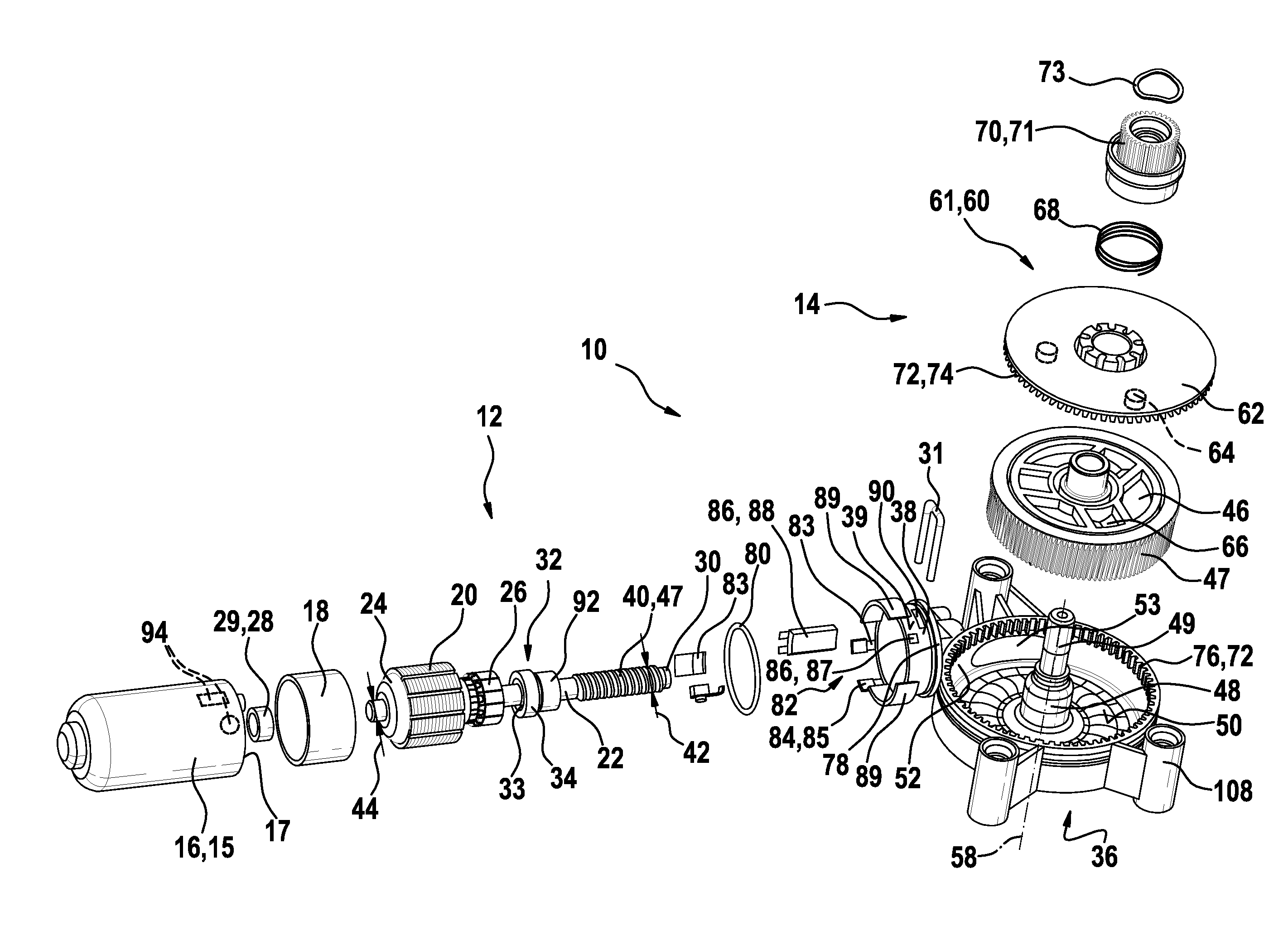
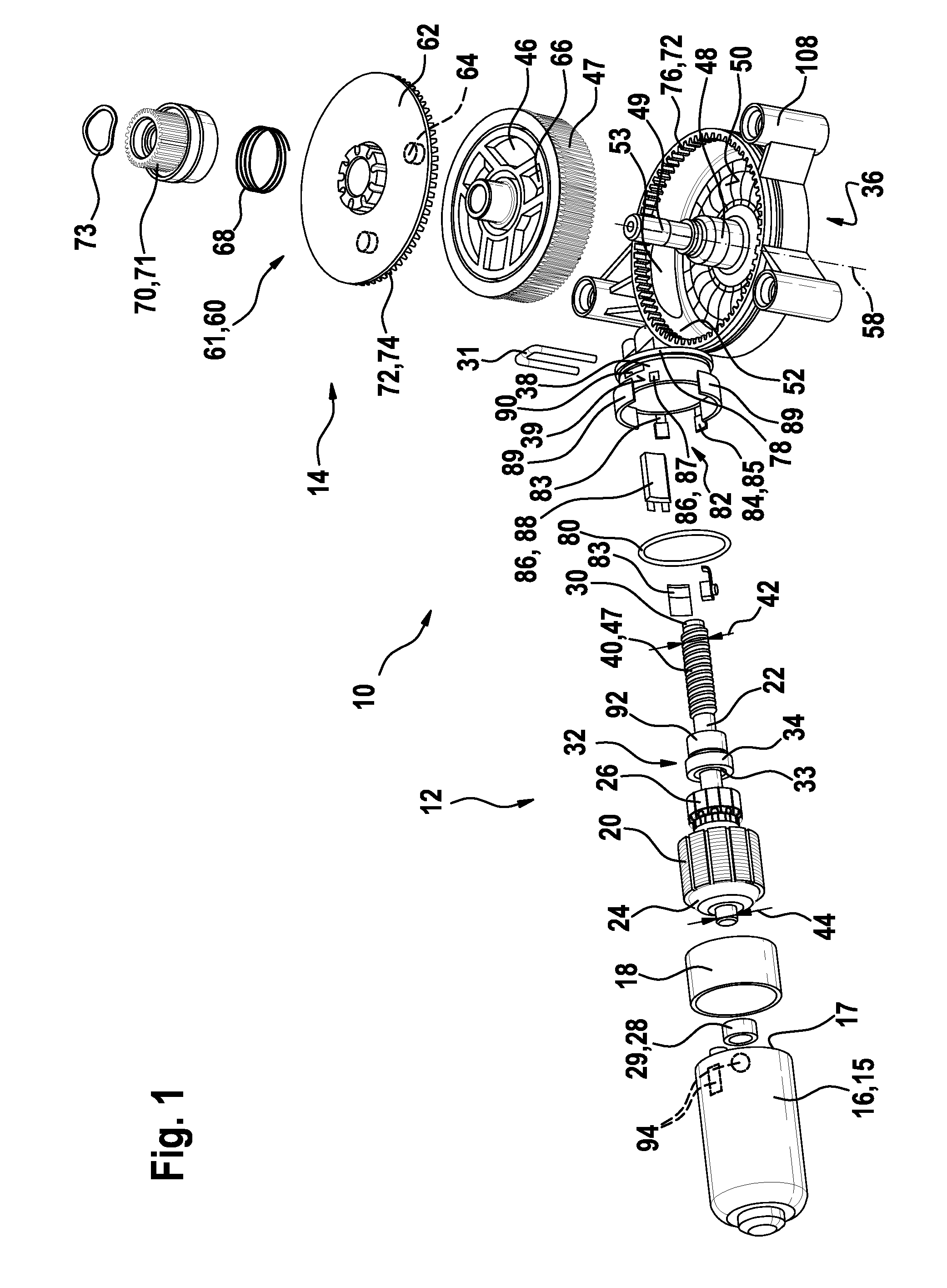
[0024]FIG. 1 shows a transmission drive unit 10 which has a drive motor 12 and a transmission 14. The drive motor 12 has a pole pot 16 as motor housing 15, in which a toric magnet 18 is arranged as exciter magnet. In the exemplary embodiment, the toric magnet 18 is configured as a high energy permanent magnet which contains NdFnB as rare earth material. A laminate core 20 having a plurality of laminations 21 is arranged within the toric magnet 18, which laminate core 20 is fastened on a drive shaft 22. The stack of laminations 20 has an electric winding 24 which is connected to a commutator 26. The drive shaft 22 is mounted in the pole pot 16 by means of a sliding bearing 28 which is configured here as a sintered bronze bush 29. Here, the sliding bearing 28 is configured as a floating bearing, as a result of which the drive shaft 22 can be displaced in the sliding bearing 28 in the axial direction 23. A ball bearing 32 which, after final assembly, is fixed firmly in the transmission...


PUM


Abstract

Transmission drive unit (10), in particular for adjusting movable parts in the motor vehicle, having a drive motor (12) and a transmission (14) which is driven thereby, wherein the transmission (14) has an output element (70) and a self-locking device (60) with a locking element (63, 55), and the locking element locks the transmission (12) with respect to torques which are applied to the transmission (12) by the output element (70), wherein the transmission (12) with its transmission toothing (47) and a motor shaft bearing (32, 28) is designed to have optimized efficiency and minimal friction, and the drive motor (12) has, as an exciter magnet, a sleeve-shaped annular magnet (18) which is arranged in a pole pot (16) which forms a magnetic return.

Description

BACKGROUND OF THE INVENTION[0001]The invention relates to a transmission drive unit having a self-locking device, in particular for adjusting movable parts in the motor vehicle.[0002]DE 197 53 106 C2 has disclosed a load torque lock which is installed in a drive train and, when the drive is at a standstill, automatically locks the torques which are introduced by the output means. In contrast, the torques which are introduced from the drive side are transmitted in both rotational directions. To this end, a drive shaft is penetrated by the attachment components of an output shaft. Between these two shafts which can be rotated counter to one another, radial webs and clamping and locking elements are arranged which permit or lock a rotation with respect to a clamping ring unit as a function of the drive-side or output-side introduction of the torques. A load torque lock of this type comprises a multiplicity of individual parts which are complicated to assemble and require a large amount...

Claims


Application Information

Patent Timeline
Patent Type & Authority Patents(United States)
IPC IPC(8): H02K7/102E05F11/50F16H1/16H02K1/17H02K7/116
CPCH02K7/1166H02K7/102F16H1/16H02K1/17E05Y2900/55E05F11/505E05Y2201/49H02K7/116
Inventor MILI, TAREKLAUK, DETLEFMERKELBACH, UWE
Owner ROBERT BOSCH GMBH
Why Eureka
Try Eureka