Fuel injector

a fuel injector and fuel technology, applied in the direction of fuel injection apparatus, fuel feed system, spraying apparatus, etc., can solve the problems of achieve the effect of less fuel leakage during operation

Inactive Publication Date: 2014-11-25
ROBERT BOSCH GMBH
View PDF19 Cites 4 Cited by
  • Summary
  • Abstract
  • Description
  • Claims
  • Application Information

AI Technical Summary

Benefits of technology

[0007]In contrast, the fuel injector of the exemplary embodiment of the present invention having the characterizing feature of the main claim has the advantage that, because of the stiffness-reducing elements provided on the valve-seat member and / or on the valve-closure member, the seat area of the fuel injector is made elastically softer, and therefore eccentricities at the seat contact points are elastically pressed over by the contact force. The fuel leakage during operation therefore becomes less. The wear of the fuel injector thereby becomes less as well, because due to the elastic conformation of the two seat elements, the contact force is distributed on a larger seat area. The contact force may also be selected to be less. The wear and the operating speed of the valve are positively influenced in this manner.
[0008]An especially positive effect is achieved if both the valve-seat area and the valve-closure member are provided with stiffness-reducing elements, an optimal conformation of the two components thereby resulting.
[0010]To reduce the stiffness of the valve-seat member, it is likewise advantageous if it is made thin-walled, so that it becomes flexible or soft in this thin-walled area. The stiffness is reduced still further if the valve-closure member has both an outer circumferential recess in the form of a circumferential groove, and moreover a second stiffness-reducing recess in an inner area.

Problems solved by technology

However, in this type of fuel injectors, eccentricities, caused by the manufacturing process, of the seat contact points at the valve needle and at the valve seat often lead to leakages of fuel during operation of the valve.
The above-mentioned fuel injectors having a spherical valve-seat member and hollow frustoconical valve-seat member have the disadvantage that eccentricities of the seat contact points at the valve needle and at the valve seat, caused by the manufacturing process, lead to leakages of fuel during operation.

Method used


Image

  • Fuel injector
  • Fuel injector
  • Fuel injector

Examples


Embodiment Construction

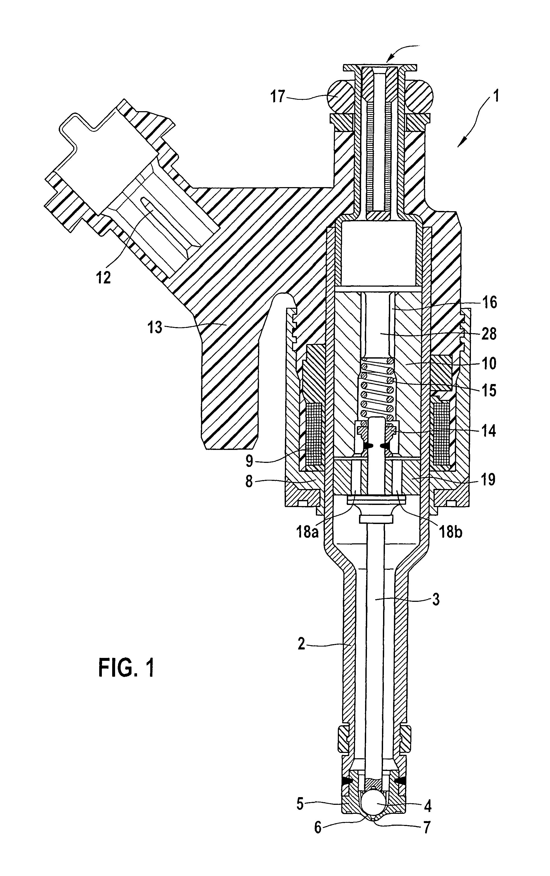
[0020]FIG. 1 shows a schematic cross-section through a fuel injector 1. Fuel injector 1 is configured in the form of a fuel injector for fuel-injection systems of mixture-compressing internal combustion engines with externally supplied ignition. Fuel injector 1 is particularly suited for the direct injection of fuel into a combustion chamber (not shown) of an internal combustion engine.

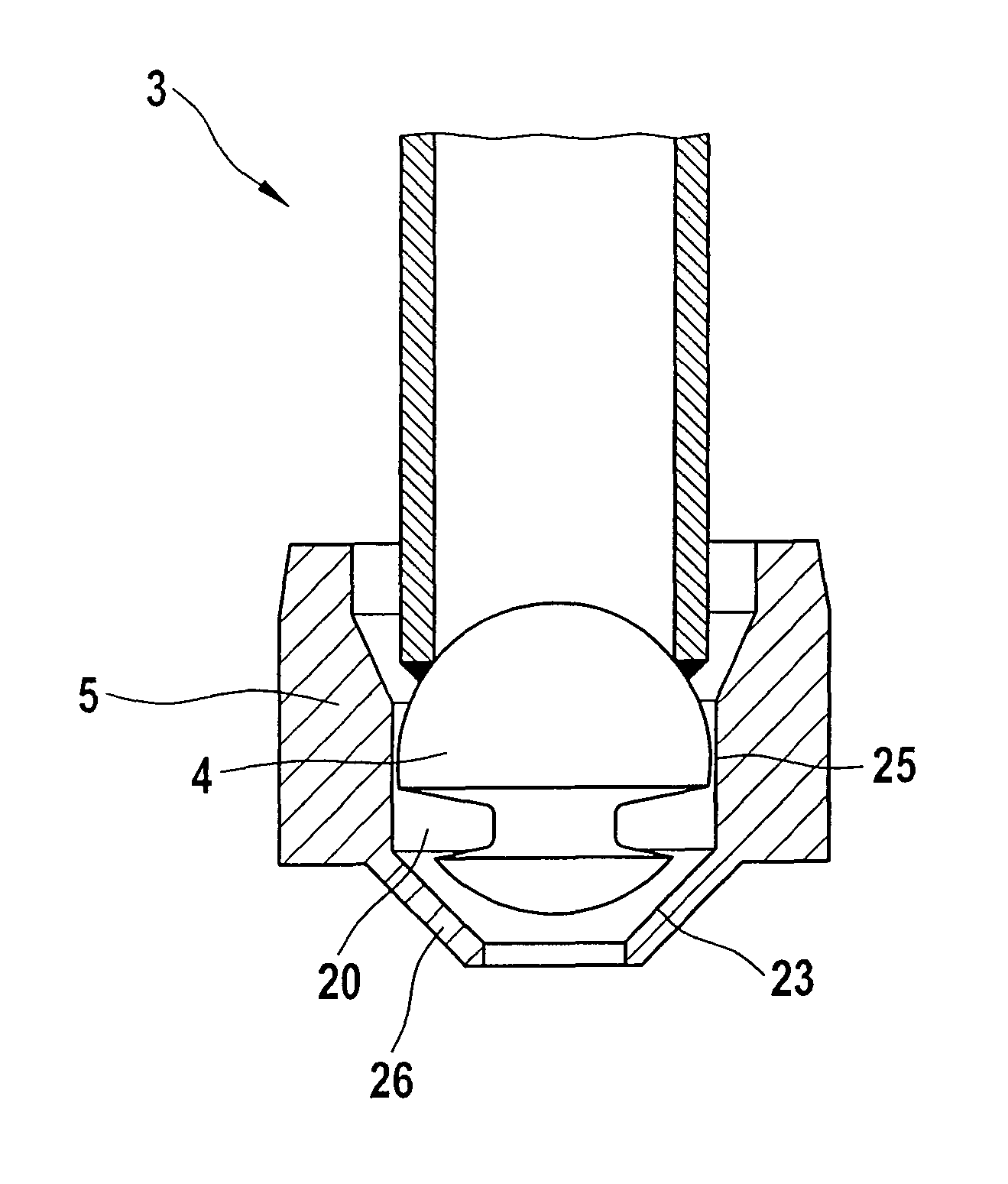
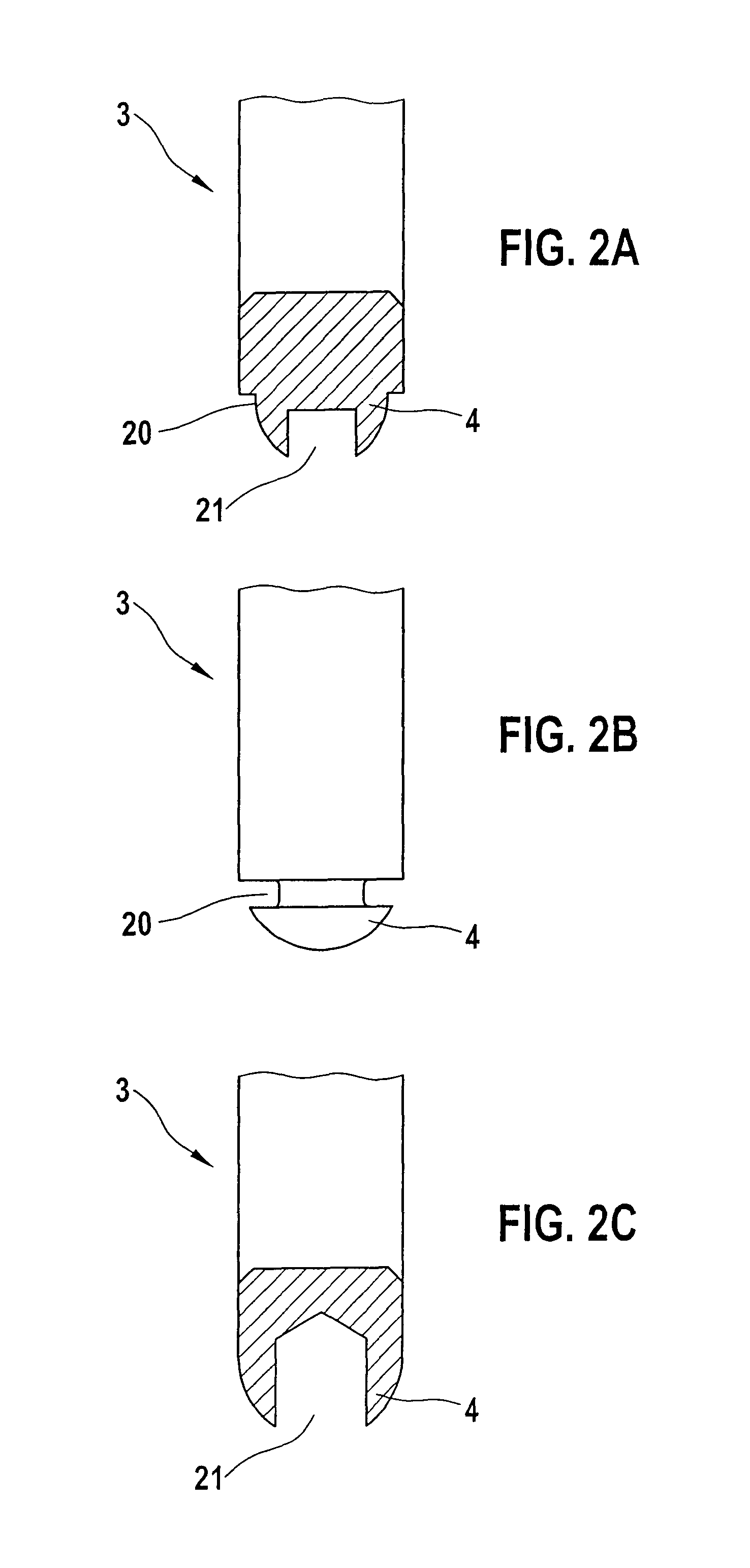
[0021]Fuel injector 1 is made up of a nozzle body 2 in which a valve needle 3 is positioned. Valve needle 3 is in operative connection with a spherical valve-closure member 4, which cooperates with a valve-seat surface 6, located on a valve-seat member 5, to form a sealing seat. In the exemplary embodiment, fuel injector 1 is an inwardly opening, electromagnetically actuated fuel injector 1 which has a spray-discharge orifice 7.

[0022]Solenoid coil 9 is wound on a coil brace which rests against an inner pole 10 of solenoid coil 9. Inner pole 10 and external pole 8 are separated from each other by a gap...


PUM


Abstract

A fuel injector, particularly for the direct injection of fuel into a combustion chamber of an internal combustion engine, has an actuator for actuating a valve needle; at a spray-discharge end, the valve needle having a valve-closure member that, together with a valve-seat surface configured on a valve-seat member, forms a sealing seat at a seat-contact point; the valve-seat member and / or the valve-closure member being provided with at least one stiffness-reducing element.

Description

FIELD OF THE INVENTION[0001]The present invention is based on a fuel injector of the type set forth in the main claim.BACKGROUND INFORMATION[0002]Inwardly-opening injection valves, both for direct injection in the high-pressure area and for manifold injection in the low-pressure area, usually have a valve seat in a ball / cone type of construction. That is, at the sealing point formed with the valve seat, the valve needle is configured with a ball or has a spherical form, and the valve seat is conical or hollow frustoconical.[0003]However, in this type of fuel injectors, eccentricities, caused by the manufacturing process, of the seat contact points at the valve needle and at the valve seat often lead to leakages of fuel during operation of the valve.[0004]A fuel injector provided with a spherical closing member is discussed, for example, in the German Patent DE 198 59 484 A1. A fuel injector for high-pressure injection of fuel from a central high-pressure delivery line into combustio...

Claims


Application Information

Patent Timeline
Patent Type & Authority Patents(United States)
IPC IPC(8): F02M51/06F02M61/16F02M61/18F02M61/10F02M61/06F02M61/04
CPCF02M61/1873F02M61/166F02M61/1893F02M2200/9015F02M61/1886F02M61/188Y10S239/90
Inventor MUELLER, MARTIN
Owner ROBERT BOSCH GMBH
Why Eureka
Try Eureka