Optical fiber clamping mechanism and optical fiber connector using the same

a technology of optical fiber connector and clamping mechanism, which is applied in the direction of optics, instruments, optical light guides, etc., can solve the problems of inconvenient or precise manner of joining the optical fiber stub and the optical fiber together, and the liquid of matching is easily evaporated

Active Publication Date: 2014-11-25
HONG FU JIN PRECISION IND (SHENZHEN) CO LTD +1
View PDF20 Cites 0 Cited by
  • Summary
  • Abstract
  • Description
  • Claims
  • Application Information

AI Technical Summary

Benefits of technology

[0005]In the Fiber To The Home (FTTH) field, many optical fiber connectors are needed for connecting the optical fiber. An optical fiber connector generally includes an optical ferrule with an optical fiber stub already terminated in the optical ferrule, an optical fiber holder, and a clamp sleeve sleeved on the optical fiber holder to fasten an optical fiber. To improve the quality of optical coupling and minimize Fresnel losses of the optical fiber connector, there are two manners of securing a joint between the optical fiber stub and the optical fiber. In a first manner, a matching liquid is injected in the optical fiber holder. However, the matching liquid evaporates easily. In a second manner, the optical fiber stub and the optical fiber are joined together by melting them together. However, the second manner is not convenient or precise enough to join the optical fiber stub and the optical fiber together.

Problems solved by technology

However, the matching liquid evaporates easily.
However, the second manner is not convenient or precise enough to join the optical fiber stub and the optical fiber together.

Method used


Image

  • Optical fiber clamping mechanism and optical fiber connector using the same
  • Optical fiber clamping mechanism and optical fiber connector using the same
  • Optical fiber clamping mechanism and optical fiber connector using the same

Examples


Embodiment Construction

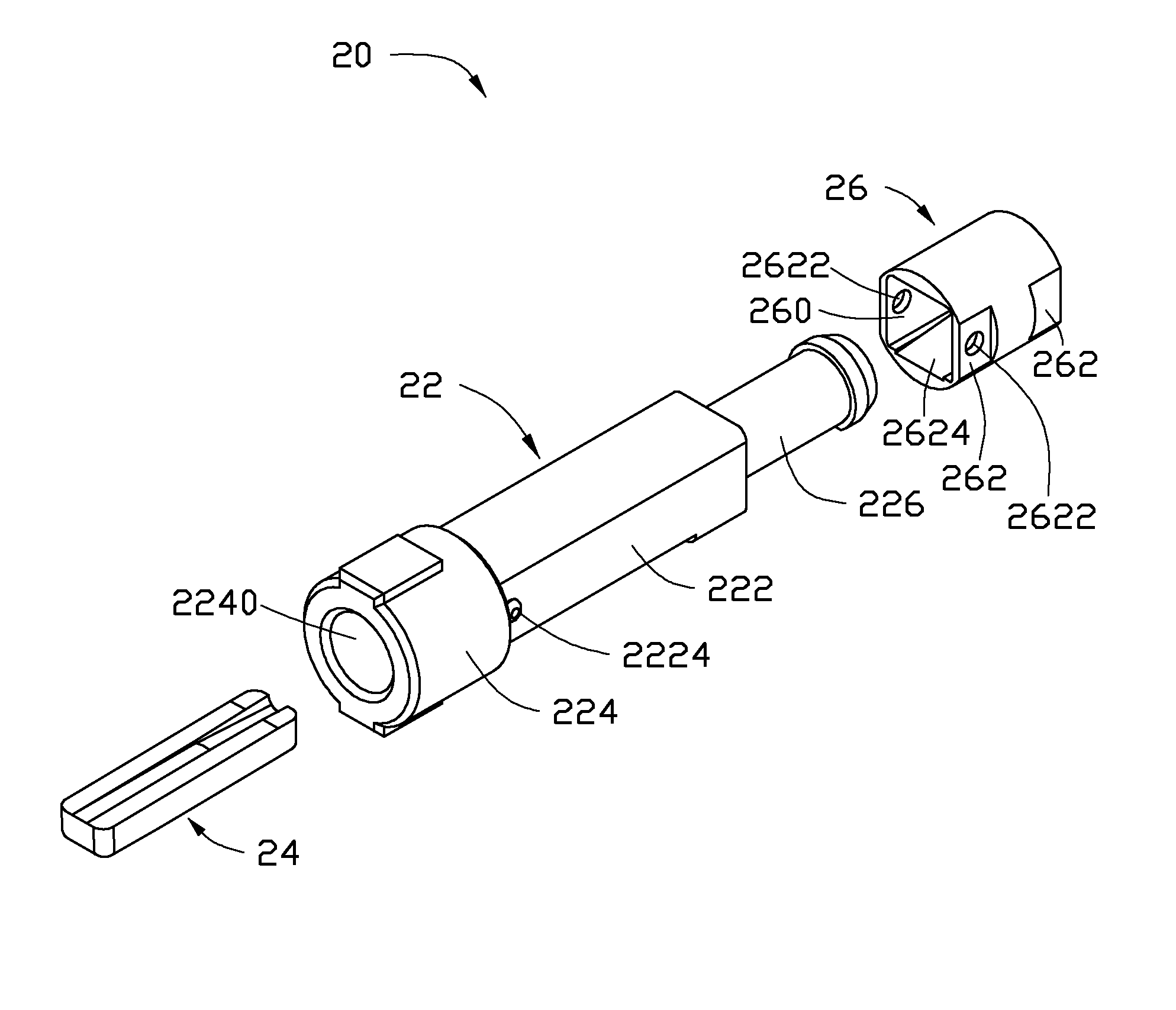
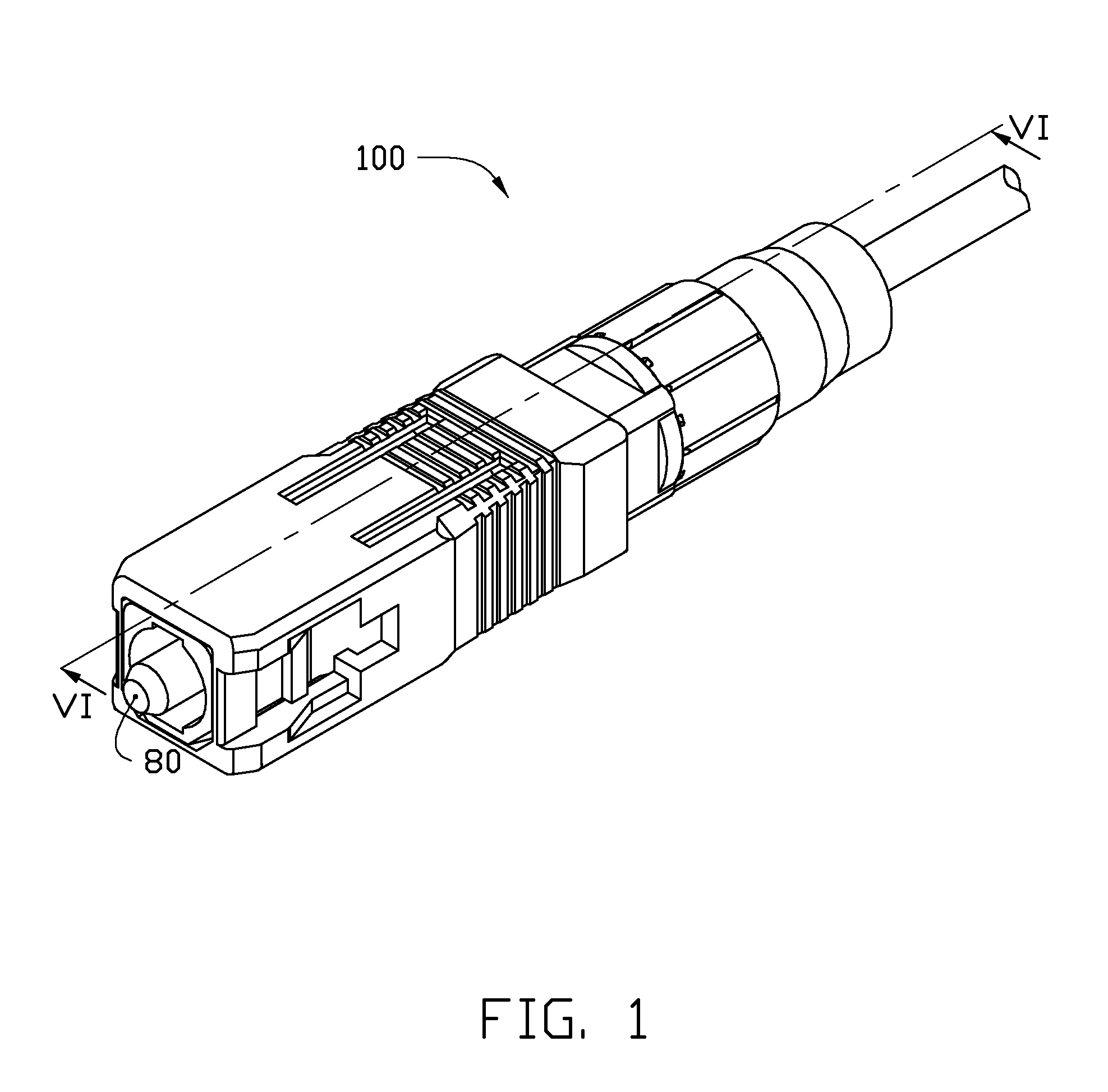
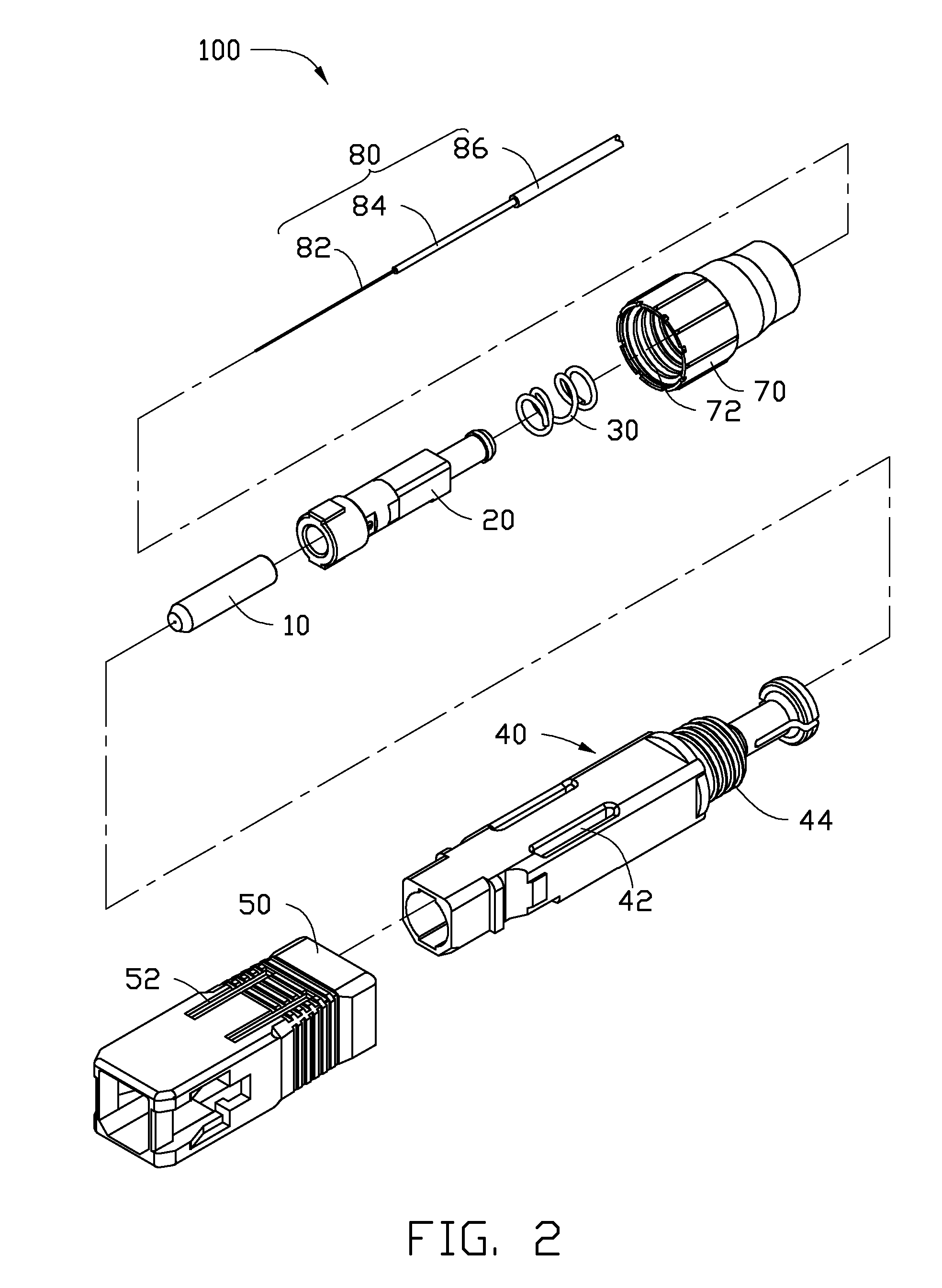
[0019]FIGS. 1 and 2 show an embodiment of an optical fiber connector 100. The optical fiber connector 100 includes an optical fiber ferrule 10, a fixing module 20, an elastic member 30, an inner housing 40, an outer housing 50, and a boot 70. The optical fiber ferrule 10 is positioned on one end of the fixing module 20. The elastic member 30 is sleeved on the other end of the fixing module 20 away from the optical fiber ferrule 10. The inner housing 40 is sleeved on the fixing module 20. The outer housing 50 is sleeved on the inner housing 40. The boot 70 is sleeved on an end of the inner housing 40 away from the outer housing 50. In an illustrated embodiment, the optical fiber connector 100 is a Subscriber Connector (SC) optical fiber connector. The optical fiber connector 100 grips a cable 80. The cable 80 includes an optical fiber 82, an inner coating 84 formed on the optical fiber 82, and an outer coating 86 formed on the inner coating 84. To facilitate the gripping of the cable...


PUM


Abstract

A fixing module for gripping an optical fiber includes a support member, a fastening member, and a locking member. The support member includes a fixing portion defining a receiving portion. The fastening member comprises a first resisting portion and a second resisting portion slantingly connected with the first resisting portion. The first resisting portion comprises a first resisting surface facing the bottom of the receiving portion. The second resisting portion comprises a second resisting surface facing the bottom of the receiving portion. The fastening member is received in the receiving portion, and the locking member sleeved on the fixing portion. The first resisting surface and the second resisting surface resist the bottom of the receiving portion in turn as the locking member slides along the fixing portion.

Description

CROSS-REFERENCE TO RELATED APPLICATIONS[0001]This application claims all benefits accruing under 35 U.S.C. §119 from China Patent Application No. 201210100960.6, filed on Apr. 9, 2012, in the China Intellectual Property Office, the disclosure of which is incorporated herein by reference. The application is also related to co-pending applications entitled, “OPTICAL FIBER CONNECTOR AND ASSEMBLING DEVICE FOR THE SAME” Ser. No. 13 / 792,215; “FIBER END SURFACE MACHINING DEVICE AND FIBER POSITION STRUCTURE THEREOF” Ser. No. 13 / 792,218; “FIBER MACHINING DEVICE AND ASSEMBLING METHOD FOR OPTICAL FIBER CONNECTOR” Ser. No. 13 / 792,219; “OPTICAL FIBER CONNECTOR” Ser. No. 13 / 792,221; “OPTICAL FIBER CONNECTOR” Ser. No. 13 / 792,222; “OPTICAL FIBER CONNECTOR” Ser. No. 13 / 792,223.BACKGROUND[0002]1. Technical Field[0003]The present disclosure relates to optical fiber clamping mechanisms, particularly to an optical fiber connector using the optical fiber clamping mechanism.[0004]2. Description of the Rel...

Claims


Application Information

Patent Timeline
Patent Type & Authority Patents(United States)
IPC IPC(8): G02B6/38G02B6/36
CPCG02B6/3805G02B6/3879G02B6/3875G02B6/3624G02B6/387G02B6/3862G02B6/3887G02B6/3823G02B6/3858G02B6/3898G02B6/2552G02B6/3869G02B6/3888
Inventor LI, ZHI-MINGWEI, LE-PENG
Owner HONG FU JIN PRECISION IND (SHENZHEN) CO LTD
Why Eureka
Try Eureka