
Multipolar outlet for a conductor connector system

a technology of conductor connector and multi-polar outlet, which is applied in the direction of coupling device connection, electrical apparatus, two-part coupling device, etc., can solve the problems of not easy to use or install, structurally rather complex, and time-consuming, so as to achieve efficient insulation, reduce crosstalk, and facilitate installation

Active Publication Date: 2014-11-25
BKS ENG
View PDF14 Cites 19 Cited by
  • Summary
  • Abstract
  • Description
  • Claims
  • Application Information

AI Technical Summary

Benefits of technology

The proposed outlet has several advantages such as being easy to install, efficient in insulating wires from each other, and maintaining a consistent distance between different wires. These features result in a constant impedance.

Problems solved by technology

This is rather time-consuming work since more than a single service is usually required nowadays at most places of work.
Moreover it has been discovered that the aforementioned electrical transmission parameters in the connector systems of the type RJ 45 are not suitable for frequencies of over 500 MHz, and desirable magnitudes can hardly be reached.
Furthermore, although some known solutions perform well, they are structurally rather complex and not easy for the end users to use or install.

Method used


Image

  • Multipolar outlet for a conductor connector system
  • Multipolar outlet for a conductor connector system
  • Multipolar outlet for a conductor connector system

Examples


Embodiment Construction

[0022]An embodiment of the present invention will be described in the following in more detail with reference to the attached figures. Same reference numerals designate identical or corresponding parts throughout the several views.

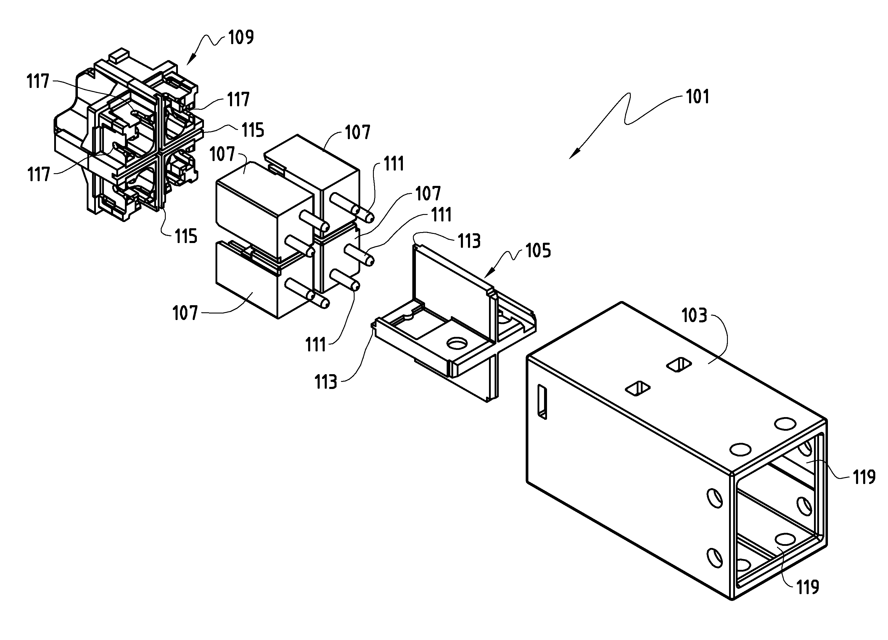
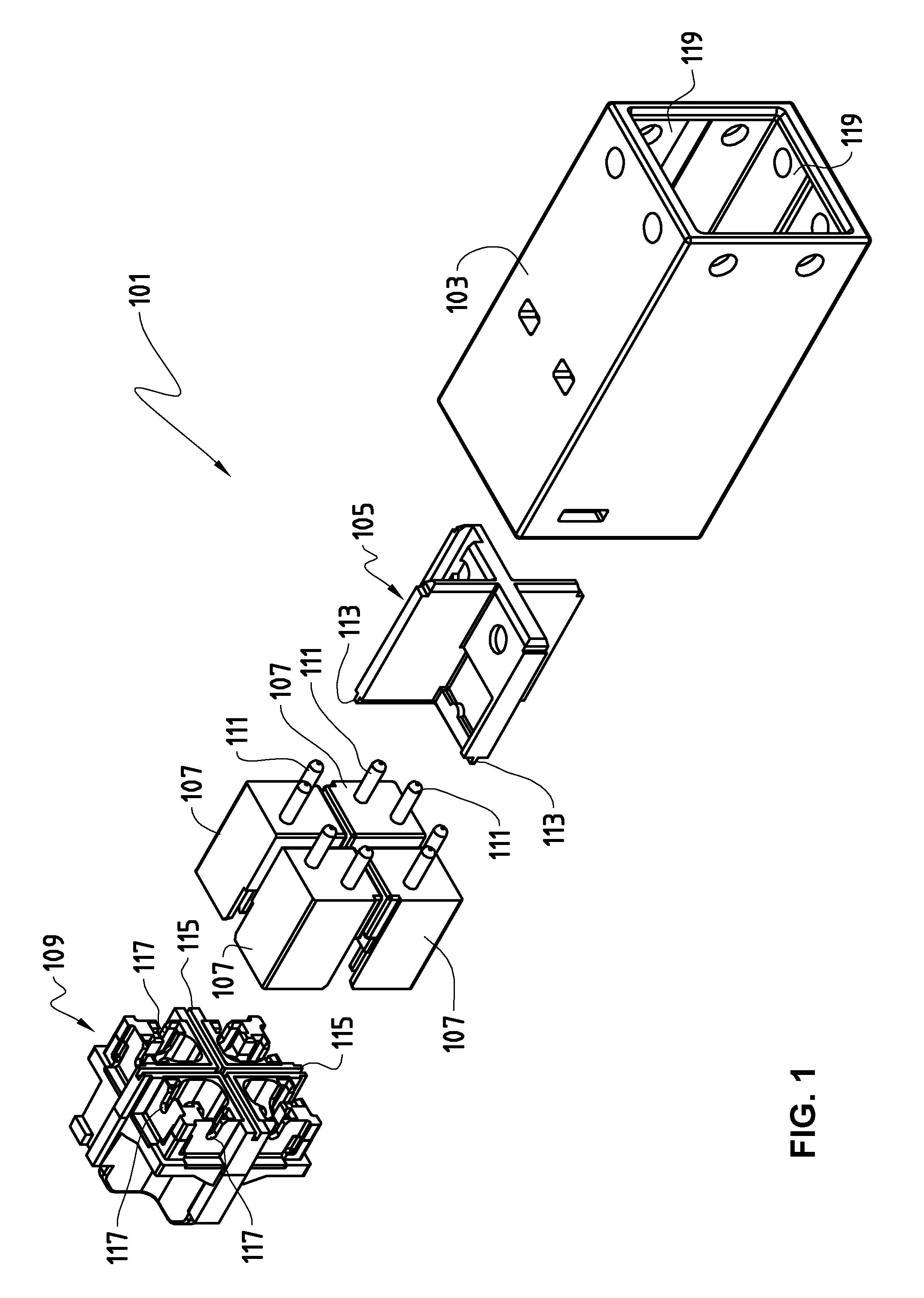
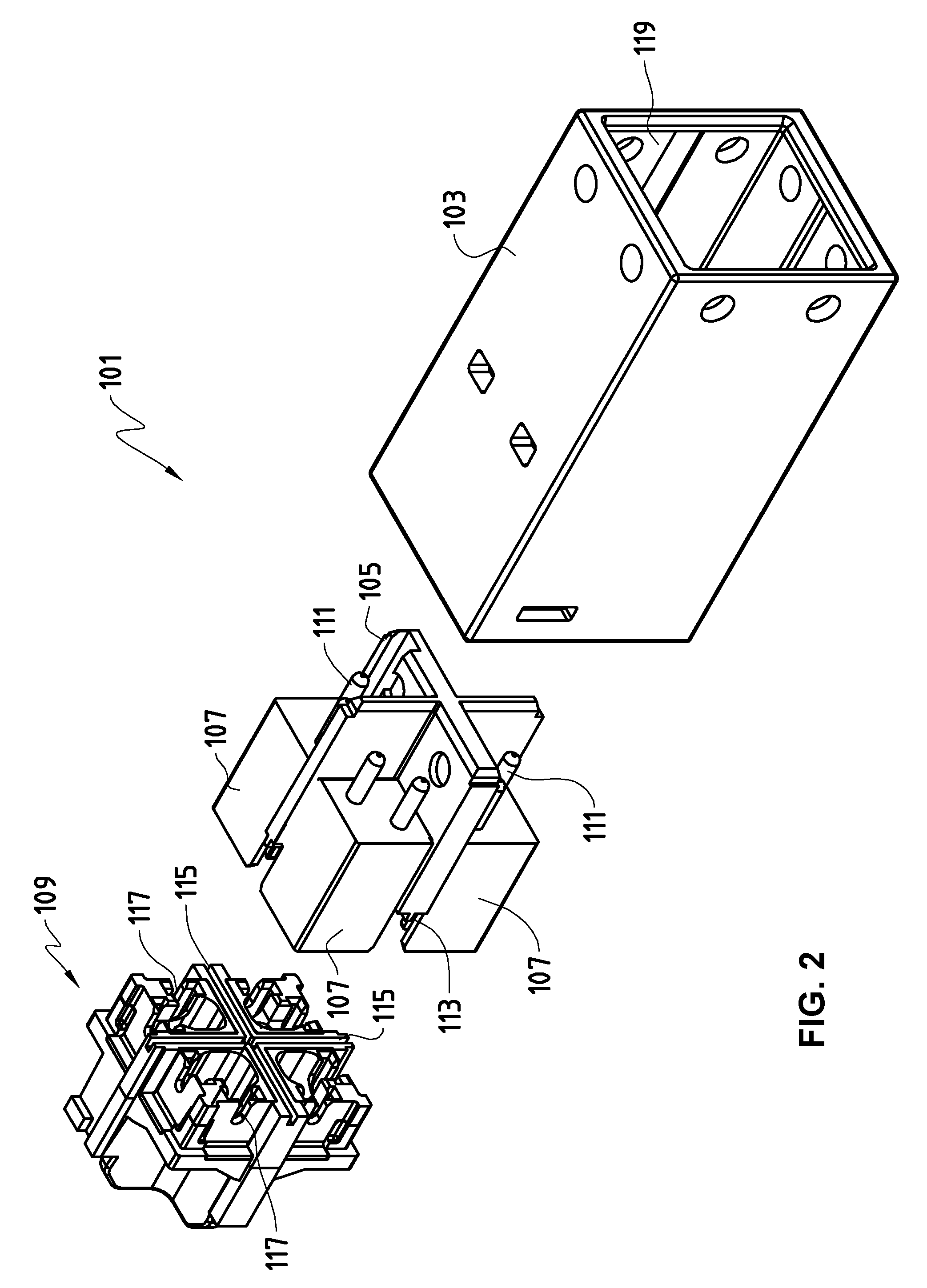
[0023]FIG. 1 illustrates an exemplary outlet 101 without cable in an exploded view seen from the front according to an embodiment of the invention. The outlet 101 in this example is made of metallic material, such as zinc die-cast. The copper layer shields the outlet interior from electromagnetic fields. Applied over the copper layer is a nickel layer, intended above all for corrosion protection. The outlet 101 comprises a housing 103 which in the assembled state of the outlet contains also a metallic partition element 105, inserts 107 and a separator 109. FIG. 2 shows the partition element 105 and the inserts 107 assembled together. The partition element 105 and the inserts 107 can also be integral with the housing 103. In FIG. 3 the partition element 105...


PUM


Abstract

A multipolar outlet for a conductor connector system. The outlet includes a housing divided into at least two chambers, each chamber including two contacts accessible from a first end of the chamber. The outlet further includes a separator for separating conductor wires and for holding the wires in place in the separator, the separator being arranged to form an end piece for the chambers at a second end, opposite to the first end, wherein the contacts are arranged to be electrically connected to the wires when the separator is in place in the housing.

Description

TECHNICAL FIELD[0001]The present invention relates to a multipolar outlet to be used in a conductor connector system for electrical and mechanical connection of electrical conductors. The invention likewise relates to a corresponding conductor connector system.BACKGROUND OF THE INVENTION[0002]The outlet according to the invention is foreseen in particular for class FA building cabling. The class determines the transmission quality of electrical signals of entire transmission lines or transmission systems from one terminal to another. In corresponding norms, such as EN 50173, limiting values are set down, for example, for the maximal cross talk attenuation, for the reflection loss, etc., as well as for the highest permissible frequencies. For class FA and future classes, working with frequencies of up to 1000 MHz and more is foreseen.[0003]The trend in technical progress is that building cabling will no longer be provided separately for telephones, electronic data processing devices,...

Claims


Application Information

Patent Timeline
Patent Type & Authority Patents(United States)
IPC IPC(8): H01R13/6585H01R13/6477H01R4/24H01R24/00H01R13/659H01R13/6592H01R13/6461
CPCH01R23/005H01R13/6585H01R13/6592H01R13/6461H01R13/6477H01R13/659H01R4/2433H01R24/00
Inventor AFFELTRANGER, WALTER
Owner BKS ENG
Learn More