Method for positioning and vehicle communication unit

a vehicle communication and positioning technology, applied in the direction of directions, instruments, measurement devices, etc., to achieve the effect of high reliability

Active Publication Date: 2014-11-25
CONTINENTAL TEVES AG & CO OHG
View PDF13 Cites 0 Cited by
  • Summary
  • Abstract
  • Description
  • Claims
  • Application Information

AI Technical Summary

Benefits of technology

[0007]It is therefore an aspect of the invention to provide more exact positioning than when the adhoc network communication is set up and to interchange the data required for this purpose with a high level of reliability within the context of vehicle-to-surroundings communication.
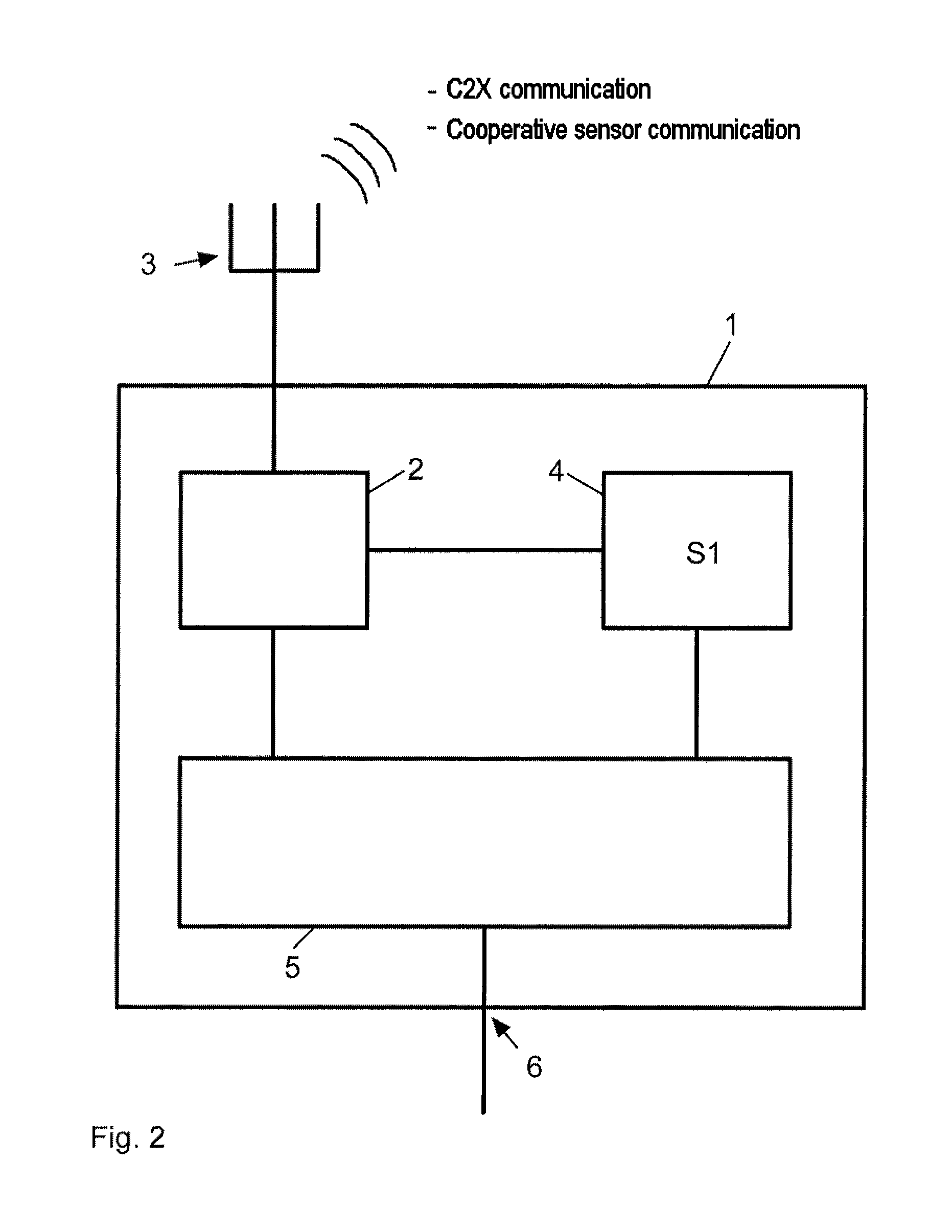
[0009]To this end, the invention proposes that the transmission and reception units of the first and second sensors of the different communication subscribers use a frequency band which is reserved for vehicle-oriented safety applications. Such a frequency band can be used for reliable communication, since this frequency band is reserved for appropriate applications. In addition, there are few collisions with other data packets since these have to side-step to other frequency bands if they are not transmitting data that are relevant to vehicle safety. Since safety applications in the vehicle are increasingly equipped with opportunities for vehicle-to-surroundings communication, it is possible to use the same transmission and reception units or antenna units both for the adhoc network communication and for the cooperative sensor communication.
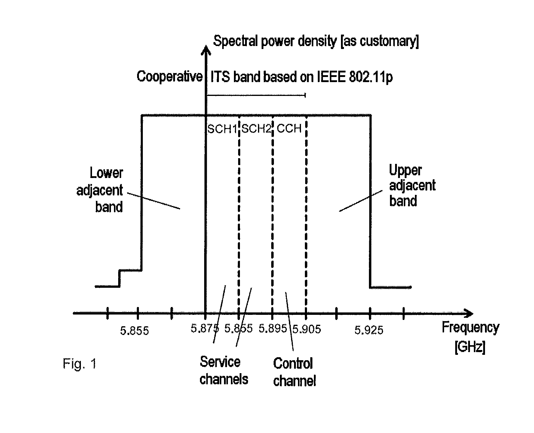
[0011]The other two channels provided within the context of the IEEE 802.11p standard (ETSI) are already in use within the context of the adhoc network communication. These are a supervisory or control channel (CCH) and service channel 1 (SCH1). Since vehicles increasingly need to be equipped with opportunities for adhoc network communication, this is a particularly favorable way of performing cooperative sensor communication at the same time and, according to aspects of the invention, using it to improve the positioning of the communication subscribers.
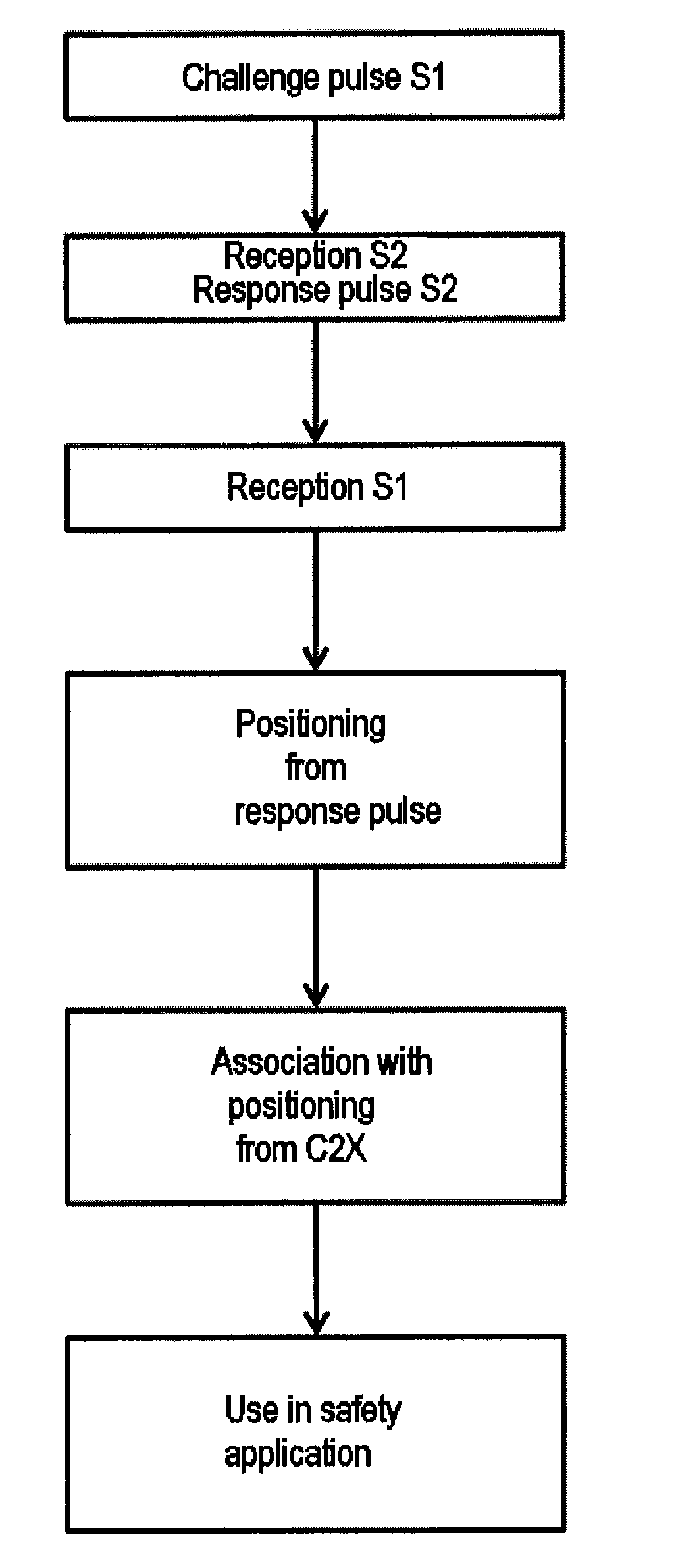
[0012]According to one preferred embodiment of the proposed method, the challenge pulse is provided with a PRN code (Pseudo Random Noise code) for the first sensor, which can be used both for interference-free communication and for identifying the first sensor. The response pulse from the second sensor is complemented particularly by an identification number, wherein the distance between the first and the second sensor is then ascertained from the propagation time of the challenge and response pulses. This allows the distance to be determined very exactly.
[0018]According to aspects of the invention, the data from the cooperative sensor communication and the adhoc network communication can be associated as early as during the execution of the adhoc network protocol stack, since both types of communication use a technically comparable communication band. This significantly speeds up the positioning, but possibly also the transmission and evaluation of further information, such as other safety-related data.
[0019]To this end, the invention can provide that further information also be transmitted with the challenge and response pulses, said information being distributed quickly on account of the high update rate in the cooperative sensor communication. This additional information, may be, in particular, safety-related data such as static type identifiers (pedestrian, cyclist, car, HGV) or the like. Besides static data, dynamic data are also suitable, such as speed, acceleration, steering wheel angle, yaw rate, brake pedal position, indicator for path prediction, etc. The dynamic data can also include data which characterize the system behavior or the driving behavior, that is to say which show how objects behave. Thus, autonomously acting systems, such as emergency braking assistants, could send data which in each case describe actions planned in the future. This prediction then allows better reactions to be obtained in the case of the surrounding objects (communication subscribers) too. In this way, it is also possible to coordinate autonomous actions better.

Problems solved by technology

In addition, there are few collisions with other data packets since these have to side-step to other frequency bands if they are not transmitting data that are relevant to vehicle safety.

Method used


Image

  • Method for positioning and vehicle communication unit
  • Method for positioning and vehicle communication unit
  • Method for positioning and vehicle communication unit

Examples


Embodiment Construction

[0028]FIG. 1 shows the channel allocation for the vehicle-to-surroundings communication within the context of the ITS standard based on ETSI for IEEE 802.11p as a spectral power density in arbitrary units as a function of the frequency in the unit GHz. The cooperative ITS band is situated at approximately 5.9 GHz and has two service channels SCH1 and SCH2 and a control channel CCH. This split is currently planned on the basis of the ETSI standard. This cooperative ITS frequency band having a width of 30 MHz has been approved in Europe exclusively for vehicle-oriented safety applications and, on the basis of current planning, is split into three channels of 10 MHz each, the vehicle-to-surroundings communication being based on a dual receiver concept, according to which two channels are always monitored. These are the control or supervisory channel CCH and one of the service channels, according to present discussions preferably the first service channel SCH1, that is to say the upper ...


PUM


Abstract

Methods and an appropriately setup communication unit for positioning in vehicle-to-surroundings communication are described, wherein the method involves a first sensor (S1) of a first communication subscriber using a transmission and reception unit to emit a challenge pulse, to which a transmission and reception unit of a second sensor (S2) of a second communication subscriber responds with a response pulse. The response pulse is received and evaluated by the first sensor (S1) and positioning is performed. In order to achieve reliable cooperative sensor communication, the transmission and reception units of the first and second sensors (S1, S2) use a frequency band (SCH2) which is reserved for vehicle-oriented safety applications.

Description

CROSS REFERENCE TO RELATED APPLICATIONS[0001]This application is the U.S. National Phase Application of PCT / EP2010 / 057909, filed Jun. 7, 2010, which claims priority to German Patent Application No. 10 2009 026 792.1, filed Jun. 5, 2009, the contents of such applications being incorporated by reference herein.FIELD OF THE INVENTION[0002]The invention relates to a method for positioning, i.e. for ascertaining the position of a communication subscriber, in vehicle-to-surroundings communication (C2X), which covers both vehicle-to-vehicle communication (C2C) and vehicle-to-infrastructure communication (C2I), and to a vehicle communication unit which is set up to carry out said method.BACKGROUND OF THE INVENTION[0003]Within the context of cooperative sensor communication, the method has provision for a first sensor of a first communication subscriber to use a transmission and reception unit to emit a challenge pulse, to which a transmission and reception unit of a second sensor of a secon...

Claims


Application Information

Patent Timeline
Patent Type & Authority Patents(United States)
IPC IPC(8): G01S13/00G01S13/78H04W40/00G08G1/123G01S13/74G01S3/02
CPCG01S13/781
Inventor STAHLIN, ULRICHMENZEL, MARCZECHA, STEPHANSCHERF, OLIVER
Owner CONTINENTAL TEVES AG & CO OHG
Why Eureka
Try Eureka