
Communication system using cables carrying ethernet signals

a communication system and ethernet technology, applied in the field of wireless communication inside buildings, can solve the problems of limited copper wire bandwidth, inability to propagate high frequency signals in the frequency bandwidth of cellular communication through copper wires without significant attenuation, and relatively expensive hardwar

Active Publication Date: 2014-11-25
CORNING OPTICAL COMM LLC
View PDF954 Cites 211 Cited by
  • Summary
  • Abstract
  • Description
  • Claims
  • Application Information

AI Technical Summary

Benefits of technology

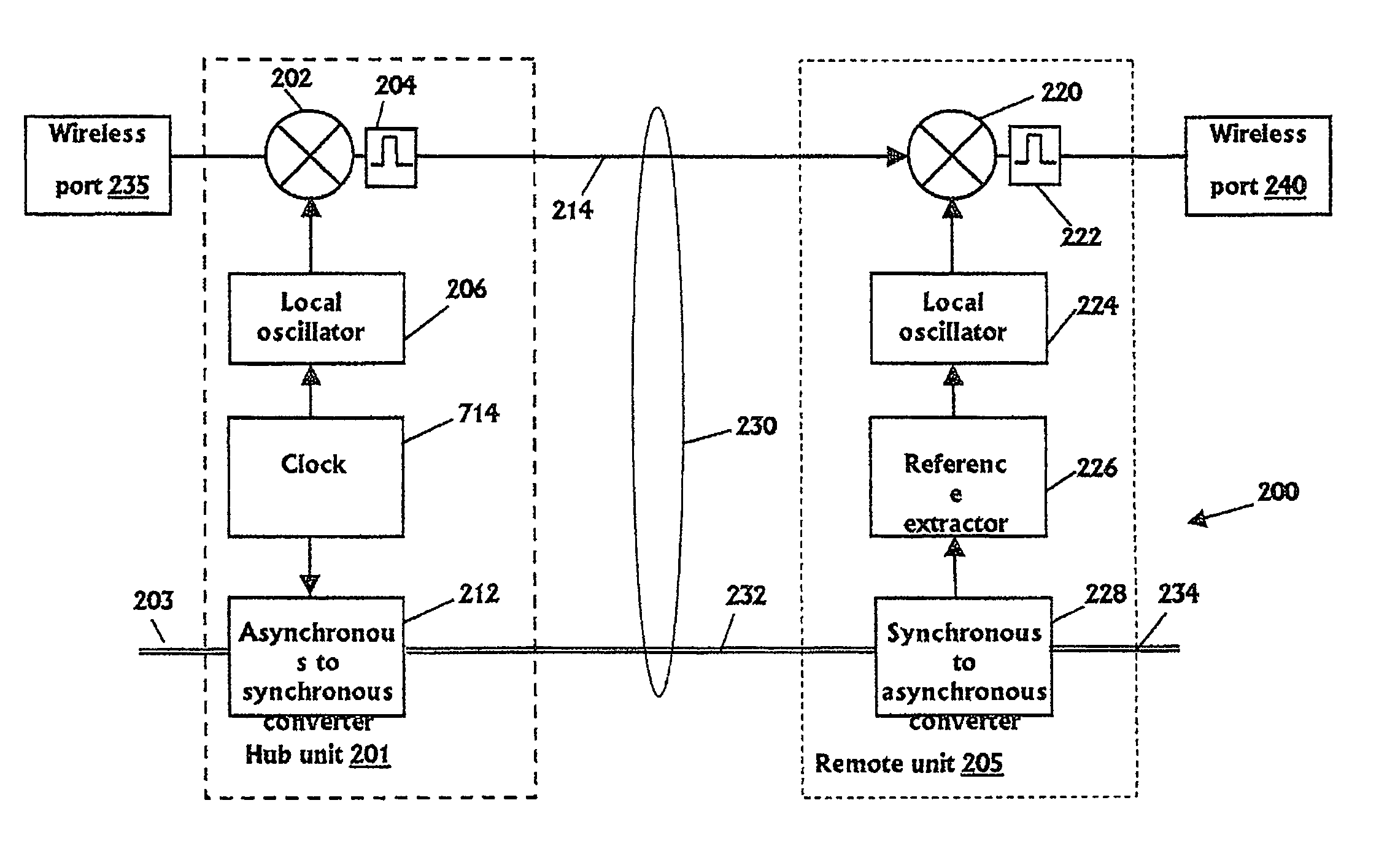
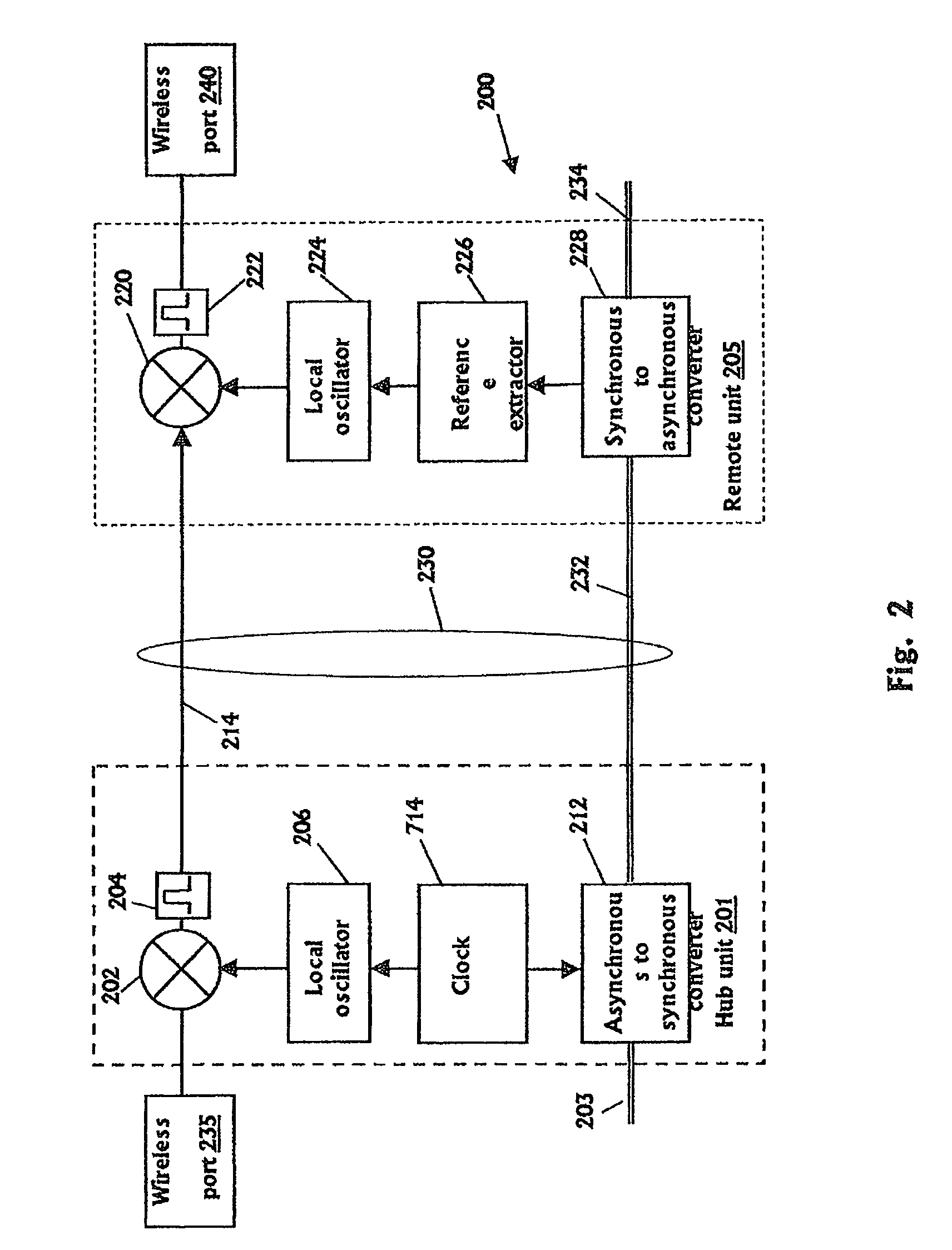
The patent describes a method for transmitting wireless signals over an Ethernet network using a single synchronous Ethernet stream. The method involves converting the wireless signal from one frequency band to another frequency band using a local oscillator and a mixer, and then shifting the signal to a different frequency band for wireless transmission. The method also includes embedding a reference signal in the Ethernet stream for recovery and synchronization purposes. The invention allows for the efficient transfer of wireless signals over Ethernet wiring, which can be useful in cellular networks and other wireless systems.

Problems solved by technology

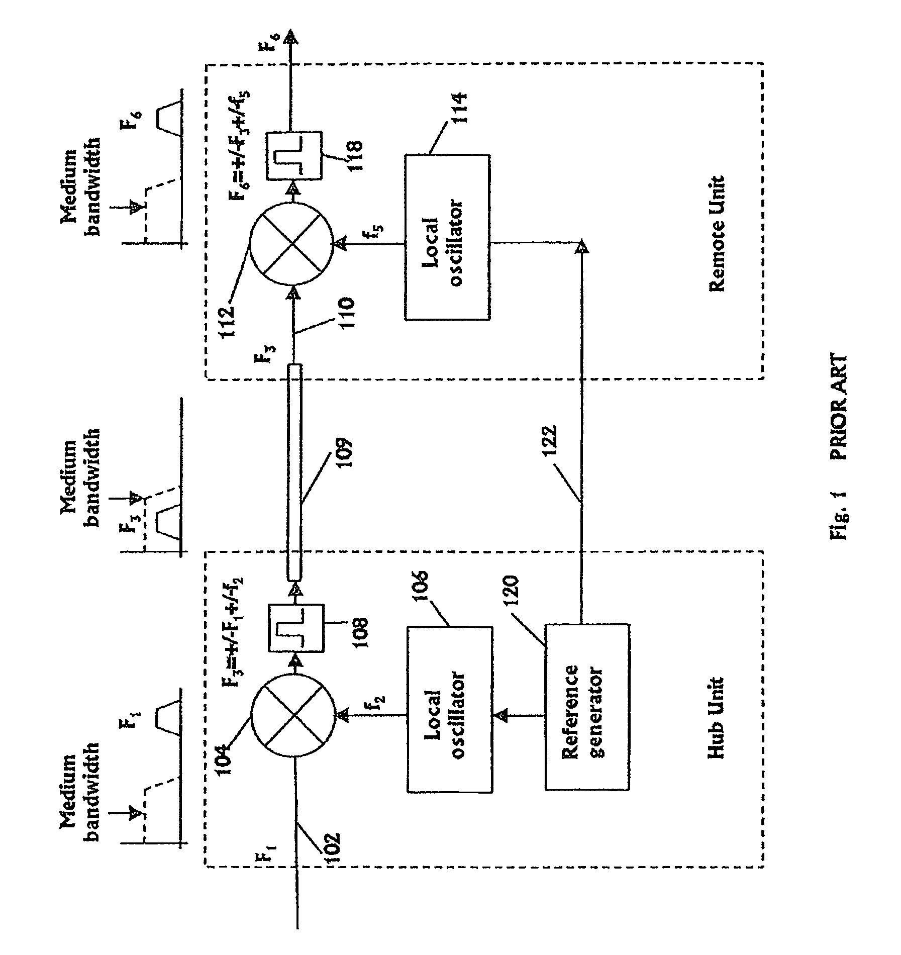
Since the bandwidth of copper wires is limited, high frequency signals in the frequency bandwidths of cellular communication are not able to propagate through the copper wires without significant attenuation.
The approach of the prior art where a special bandwidth is dedicated to the reference signal requires a dedicated special frequency band in the limited bandwidth of the wires and also requires use of a relatively expensive hardware such as sharp band pass filter, mixer in order to filter the reference signal out of the other signals.
Moreover, the transfer of reference signal through the cables creates additional interference that might block or degrade other communication channels.

Method used


Image

  • Communication system using cables carrying ethernet signals
  • Communication system using cables carrying ethernet signals
  • Communication system using cables carrying ethernet signals

Examples


Embodiment Construction

[0036]The present invention will now be described in terms of specific example embodiments. It is to be understood that the invention is not limited to the example embodiments disclosed. It should also be understood that not every feature of the methods and systems handling the described wireless and Ethernet communications is necessary to implement the invention as claimed in any particular one of the appended claims. Various elements and features of devices are described to fully enable the invention. It should also be understood that throughout this disclosure, where a method is shown or described, the steps of the method may be performed in any order or simultaneously, unless it is clear from the context that one step depends on another being performed first.

[0037]Before explaining several embodiments of the invention in detail, it is to be understood that the invention is not limited in its application to the details of construction and the arrangement of the components set for...


PUM


Abstract

It is provided a method for transmitting a wireless signal on Ethernet wiring The wireless signal is received in a hub unit for delivery to a remote unit In the hub unit the wireless signal is down converted to a down-converted frequency band for propagation on the Ethernet wiring A reference signal associated with a local oscillator used for the down conversion is embedded on a synchronous Ethernet stream that may include Ethernet data received at hub unit The synchronous Ethernet stream and the down converted wireless signal are submitted through the Ethernet wiring to the remote unit. The synchronous Ethernet stream may include data for management of electronic circuits installed in the remote unit, as well as a synchronization signal used thereof A converted replica of the first signal may be included in digital form in frames of the synchronous Ethernet stream.

Description

RELATED APPLICATIONS[0001]This patent application is a National Stage of PCT / IB2010 / 050541 filed on Feb. 7, 2010, which claims priority of U.S. Provisional Patent Application No. 61 / 150,764 filed Feb. 8, 2009, the contents of which are incorporated herein by reference.BACKGROUND OF THE INVENTION[0002]1. Field of the Invention[0003]The invention is in the field of wireless communication inside buildings, and in particular deals with carrying wireless communication over wiring infrastructure used for Ethernet.[0004]2. Description of Related Art[0005]The invention relates to an In Building (IB) communication system for propagating wireless signals inside buildings using existing wiring infrastructure carrying Ethernet signals.[0006]Several systems and application exist today where cellular or other high frequency signals are propagated through copper wires such as telephone or Ethernet wiring. Since the bandwidth of copper wires is limited, high frequency signals in the frequency bandw...

Claims


Application Information

Patent Timeline
Patent Type & Authority Patents(United States)
IPC IPC(8): H04L12/413H04W4/00
CPCH04L12/413
Inventor SHAPIRA, ISAACSABAN, OFERHAZANI, AMI
Owner CORNING OPTICAL COMM LLC
Learn More