Electric power steering system

a technology of electric power steering and steering wheel, which is applied in the direction of non-deflectable wheel steering, position/direction control, vehicle position/course/altitude control, etc., can solve the problem that the execution of the current limit cannot be avoided, the phase current that can actually flow has a limit, and the motor torque that arises near the asymptote is unavoidable, so as to facilitate fine steering angle adjustment and improve steering feel. , the effect of steering feel

Active Publication Date: 2014-11-25
JTEKT CORP
View PDF8 Cites 4 Cited by
  • Summary
  • Abstract
  • Description
  • Claims
  • Application Information

AI Technical Summary

Benefits of technology

[0010]The present invention is made in view of the problems with the related art described above and provides an electric power steering system that can improve the steering feel in the continuous control after the occurrence of the energization failure.

Problems solved by technology

Examples of the energization failure include the break in a power line that connects between the driver circuit and a motor coil in each phase, and an open fault (permanent open fault) of each switching element that configures the driver circuit.
However, the stop of the motor as a drive source results in a certain increase of a steering effort that is required of a driver.
Although the uniform motor torque can be generated through two-phase energization in the secant curve pattern or the cosecant curve pattern, the phase current that can actually flow has a limit, and a drop in the motor torque that arises near the asymptote due to the execution of the current limit is unavoidable.
Even if the motor coil and the driver circuit as well as a power supply line are configured to be the dual systems, as long as the configuration utilizes the motor torque of both systems, the power drop due to a stop of the energization of one system is unavoidable.

Method used


Image

  • Electric power steering system
  • Electric power steering system
  • Electric power steering system

Examples


Embodiment Construction

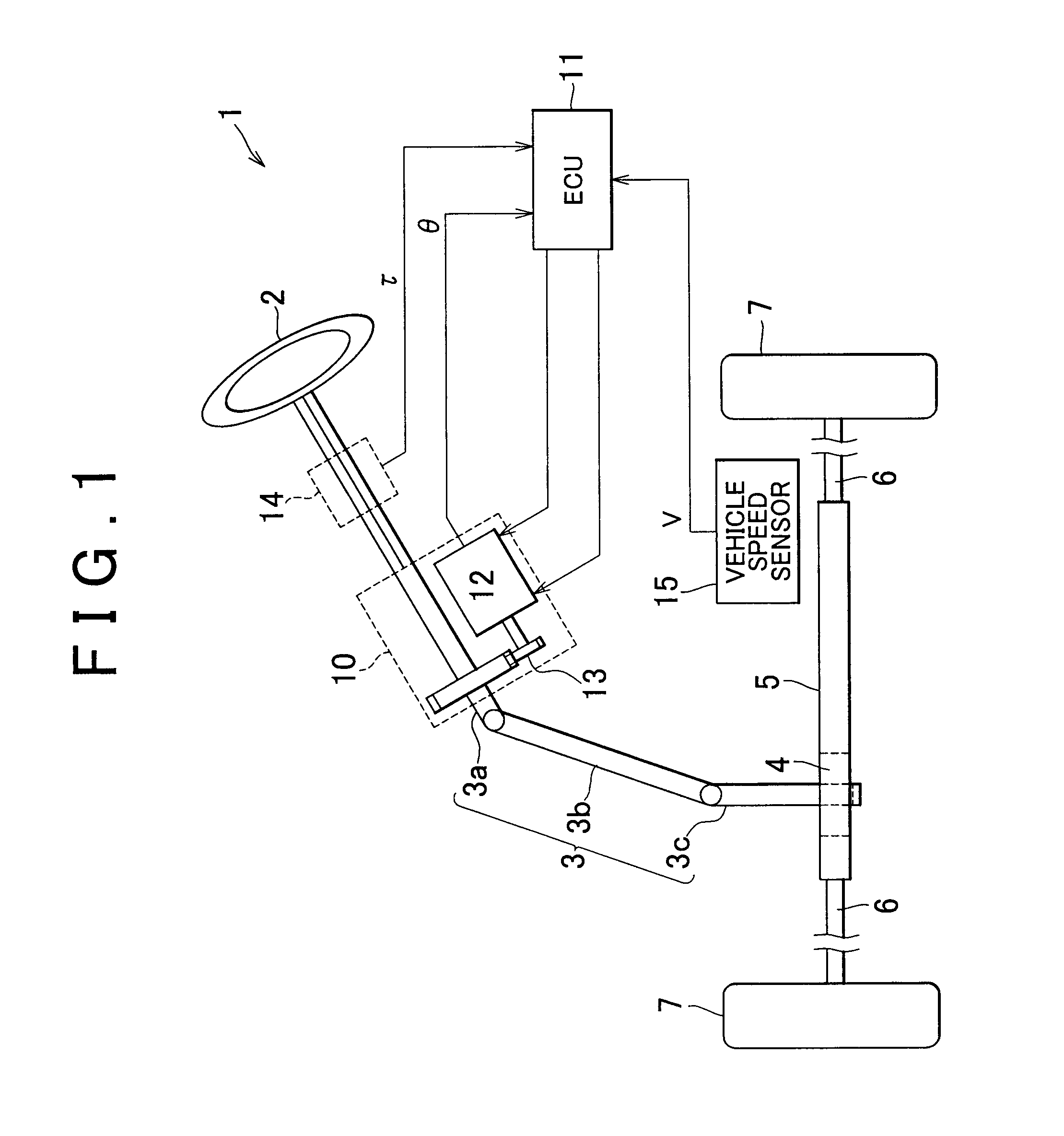
[0038]Hereinafter, a first embodiment that embodies the present invention will be described with reference to the attached drawings. As shown in FIG. 1, an electric power steering system (EPS) 1 of the present embodiment includes a steering wheel 2, a steering shaft 3, a rack-and-pinion system 4, and a rack shaft 5 so that the steering shaft 3 to which the steering wheel 2 is fixed is connected to the rack shaft 5 through the rack-and-pinion system 4. The rotation of the steering shaft 3 associated with a steering operation is converted into reciprocating movement of the rack shaft 5 by the rack-and-pinion system 4. The steering shaft 3 of the present embodiment includes a column shaft 3a, an intermediate shaft 3b, and a pinion shaft 3c such that those shafts are connected in this order. The reciprocating movement of the rack shaft 5 associated with the rotation of the steering shaft 3 is transmitted to steering knuckles (not shown) through tie rods 6 that are connected to ends of t...


PUM


Abstract

In an electric power steering system, a control signal output section outputs independent dual-system control signals to driver circuits that are disposed in connection with independent dual-system motor coils. The control signal output section gives high priority to the output of the control signal to the other system, when the occurrence of energization failure is detected in one system. When the energization failure occurring phase is only one phase and the value of the basic command exceeds the upper limit of the priority command, the control signal output section outputs the control signal to the driver circuit in the system where the energization failure has occurred in order to supply electric power in which the two phases other than the energization failure occurring phase are used as the energized phases on the bases of the complementary command that corresponds to the excess of the upper limit.

Description

[0001]The disclosure of Japanese Patent Applications No. 2010-200281 filed Sep. 7, 2010, including the specification, drawings and abstract is incorporated herein by references in its entirety.BACKGROUND OF THE INVENTION[0002]1. Field of the Invention[0003]The present invention relates to an electric power steering system.[0004]2. Description of the Related Art[0005]In general, an electric power steering system (EPS) has a function of detecting the occurrence of an anomaly of a motor when the energization failure occurs in any of phases of the motor (any of U, V, and W phases) due to a break in a power supply line, a contact failure of a driver circuit, or the like. Examples of the energization failure include the break in a power line that connects between the driver circuit and a motor coil in each phase, and an open fault (permanent open fault) of each switching element that configures the driver circuit. Conventionally, when such the failure is detected, the configuration that s...

Claims


Application Information

Patent Timeline
Patent Type & Authority Patents(United States)
IPC IPC(8): H02P21/06H02P29/02B62D5/04H02P21/00B62D6/00B62D119/00H02P21/05H02P21/22H02P23/04H02P27/04H02P27/08
CPCB62D5/0487H02P29/025H02P29/022B62D5/0484B62D5/0463H02P21/06B62D5/0403H02P21/0021B62D5/0478H02P29/032
Inventor SUZUKI, HIROSHI
Owner JTEKT CORP
Why Eureka
Try Eureka