Controller for electric power steering apparatus

a technology of electric power steering and control device, which is applied in the direction of steering initiation, instruments, vessel construction, etc., can solve the problems of increasing the cost of the microcomputer, so as to reduce the assist power of the steering device, prevent an excessive impact, and control simple

Inactive Publication Date: 2009-10-27
JTEKT CORP +1
View PDF8 Cites 4 Cited by
  • Summary
  • Abstract
  • Description
  • Claims
  • Application Information

AI Technical Summary

Benefits of technology

[0004]The drive signal values corresponding to the rotary position of the rotor should be calculated at high speed in order to control the drive currents of the brushless motor for generating steering assist power with a high degree of precision. Moreover, complicated and non-typological calculation should be performed to correct the target current value in accordance with the rotor rotation speed and so on in order to improve the steering feel of the vehicle driver. However, a high-performance microcomputer is required to perform these high-speed, complicated, and non-typological calculations, so that the cost of the microcomputer is increased.
[0005]Furthermore, a dedicated sub-microcomputer and hardware for monitoring circuits to monitor the abnormalities in the calculated values should be provided to perform failsafe processing. However, the provision of the dedicated sub-microcomputer and hardware for monitoring circuits to perform failsafe processing leads to a further increase in cost.

Problems solved by technology

Moreover, complicated and non-typological calculation should be performed to correct the target current value in accordance with the rotor rotation speed and so on in order to improve the steering feel of the vehicle driver.
However, a high-performance microcomputer is required to perform these high-speed, complicated, and non-typological calculations, so that the cost of the microcomputer is increased.
However, the provision of the dedicated sub-microcomputer and hardware for monitoring circuits to perform failsafe processing leads to a further increase in cost.

Method used


Image

  • Controller for electric power steering apparatus
  • Controller for electric power steering apparatus
  • Controller for electric power steering apparatus

Examples


Embodiment Construction

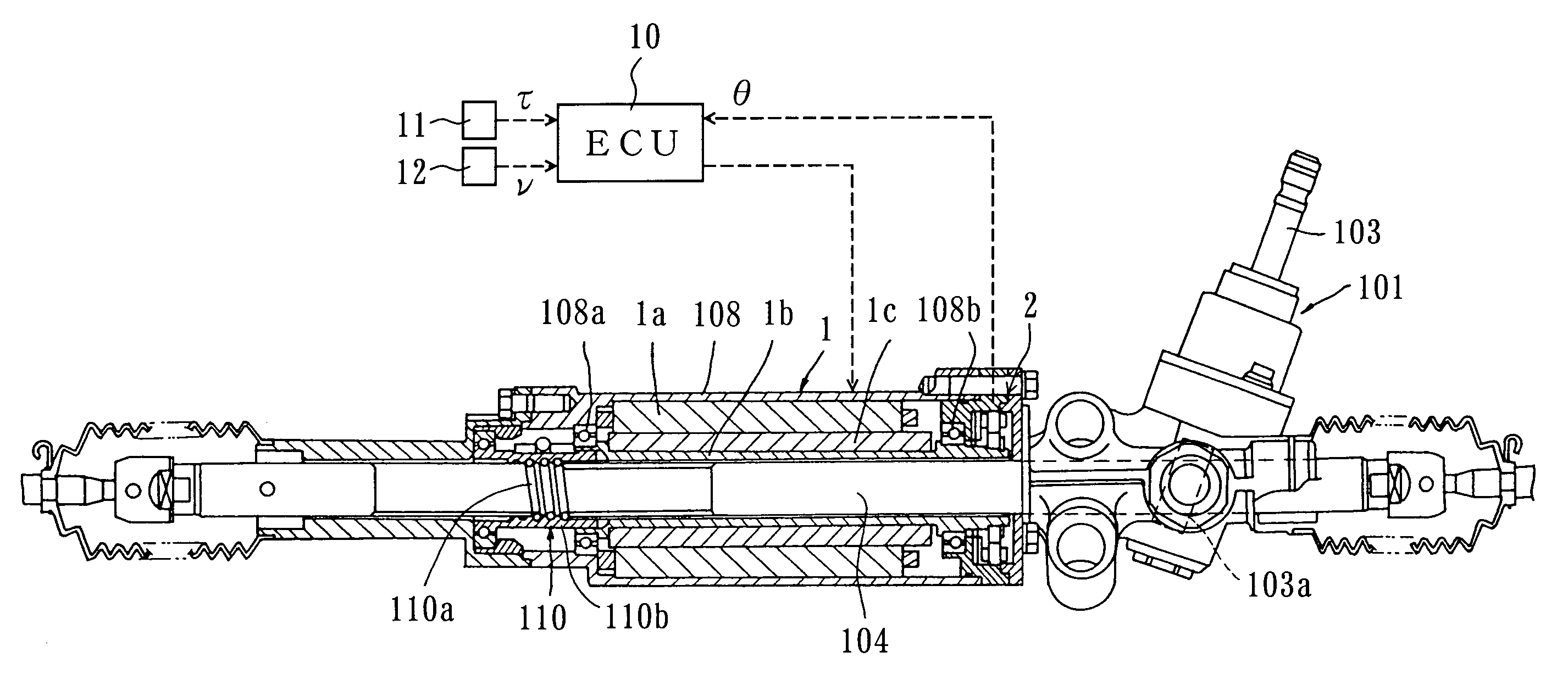
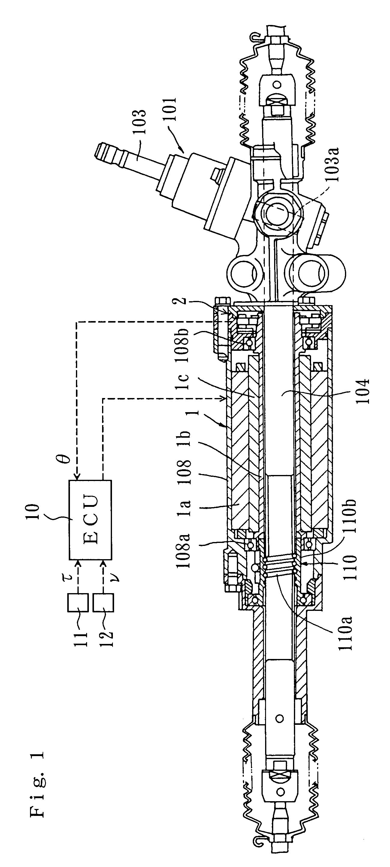
[0029]A rack and pinion type electric power steering apparatus 101 for a vehicle, shown in FIG. 1, comprises a steering shaft 103 which is rotated by steering operation, a pinion 103a provided on the steering shaft 103, a rack 104 which meshes with the pinion 103a, and a three-phase brushless motor 1 for generating steering assist power. Each end of the rack 104 is connected to a vehicle wheel (not shown in the drawing) for steering. The pinion 103a is rotated by the steering operation, whereby the rack 104 moves in its longitudinal direction along the width direction of the vehicle. The steering angle is varied by the movement of the rack 104.

[0030]The motor 1 comprises a stator 1a having coils of U, V and W phases, which is fixed to a housing 108 covering the rack 104, a tubular rotor 1b supported rotatably by the housing 108 via bearings 108a, 108b, a magnet 1c attached to the rotor 1b, and a resolver 2 by which a rotary position detection part for detecting the rotary position o...


PUM


Abstract

In a controller for an electric power steering apparatus, a target value calculation element, which calculates target values of the drive currents of a motor on the basis of a detected value of the steering torque, is constituted by a first integrated circuit provided in a chip. A drive signal value calculation element, which calculates drive signal values for driving the motor on the basis of the target values calculated by the target value calculation element, detected values of the drive currents of the motor, and a detected value of the rotary position of a rotor of the motor, is constituted by a second integrated circuit provided in another chip from the chip. A driving element drives the motor in accordance with the drive signal values. The first integrated circuit is connected communicably to the second integrated circuit. The calculation cycle of the drive signal values is set to be shorter than the calculation cycle of the target values.

Description

FIELD OF THE INVENTION[0001]The present invention relates to a controller for controlling a motor for generating steering assist power in an electric power steering apparatus.DESCRIPTION OF THE RELATED ART[0002]In a controller for an electric power steering apparatus, target values of the drive currents of a brushless motor which generates steering assist power are calculated on the basis of the steering torque. Drive signal values for driving the motor are then calculated on the basis of the calculated target values, detected values of the drive currents, and a detected value of the rotary position of the rotor. The motor is then driven by a motor driver in accordance with the calculated drive signal values.[0003]The target values of the drive currents described above are calculated using a one-chip microcomputer, the drive signal values are calculated using another one-chip microcomputer, and the two microcomputers are connected by communication lines constituted by wire harnesses...

Claims


Application Information

Patent Timeline
Patent Type & Authority Patents(United States)
IPC IPC(8): B62D5/04B62D6/00G06F19/00B62D101/00B62D119/00B62D137/00
CPCB62D5/046B62D5/0493B62D5/0463B62D5/04B62D5/14
Inventor NAGASE, SHIGEKIYUKUMATSU, NORIMITSU
Owner JTEKT CORP
Why Eureka
Try Eureka