System and method for inhibiting torque steer

a technology of torque steer and inhibiting system, which is applied in the direction of electrical control, instruments, tractors, etc., can solve the problems of high level, ineffective mitigation or inhibiting of torque steer, persistent torque steer, etc., and achieves the effect of improving the overall steering feel of vehicles and great straight-line acceleration performan

Inactive Publication Date: 2005-07-28
HONDA MOTOR CO LTD
View PDF17 Cites 4 Cited by
  • Summary
  • Abstract
  • Description
  • Claims
  • Application Information

AI Technical Summary

Benefits of technology

[0012] The system according to the invention comprises sensors that measure steering angle and transmission gear position, one or more controllers that calculate the maximum engine torque limit and estimated driver-requested engine torque, a comparator that selects a lower of the maximum engine torque and the estimated driver-requested engine torque, and a throttle angle calculator that determines the throttle angle based upon the selected engine torque and the engine speed. Because the system determines the maximum engine torque limit as a function of steering angle, the system allows for greater straight-line acceleration performance as compared to when the vehicle is being steered in a direction other than in a straight line. The invention improves the overall steering feel of vehicles equipped with steerable wheels that are power driven.

Problems solved by technology

In many driving situations however, the left / right difference in longitudinal tire force can lead to a persistent torque steer before the onset of appreciable wheel slip.
This situation is especially problematic when high levels of engine torque are applied as a vehicle is being steered in a direction other than straight on a high adhesion surface.
Thus, conventional wheel-slip based traction control systems are generally ineffective to mitigate or inhibit torque steer before a wheel-slip condition occurs.

Method used


Image

  • System and method for inhibiting torque steer
  • System and method for inhibiting torque steer
  • System and method for inhibiting torque steer

Examples


Embodiment Construction

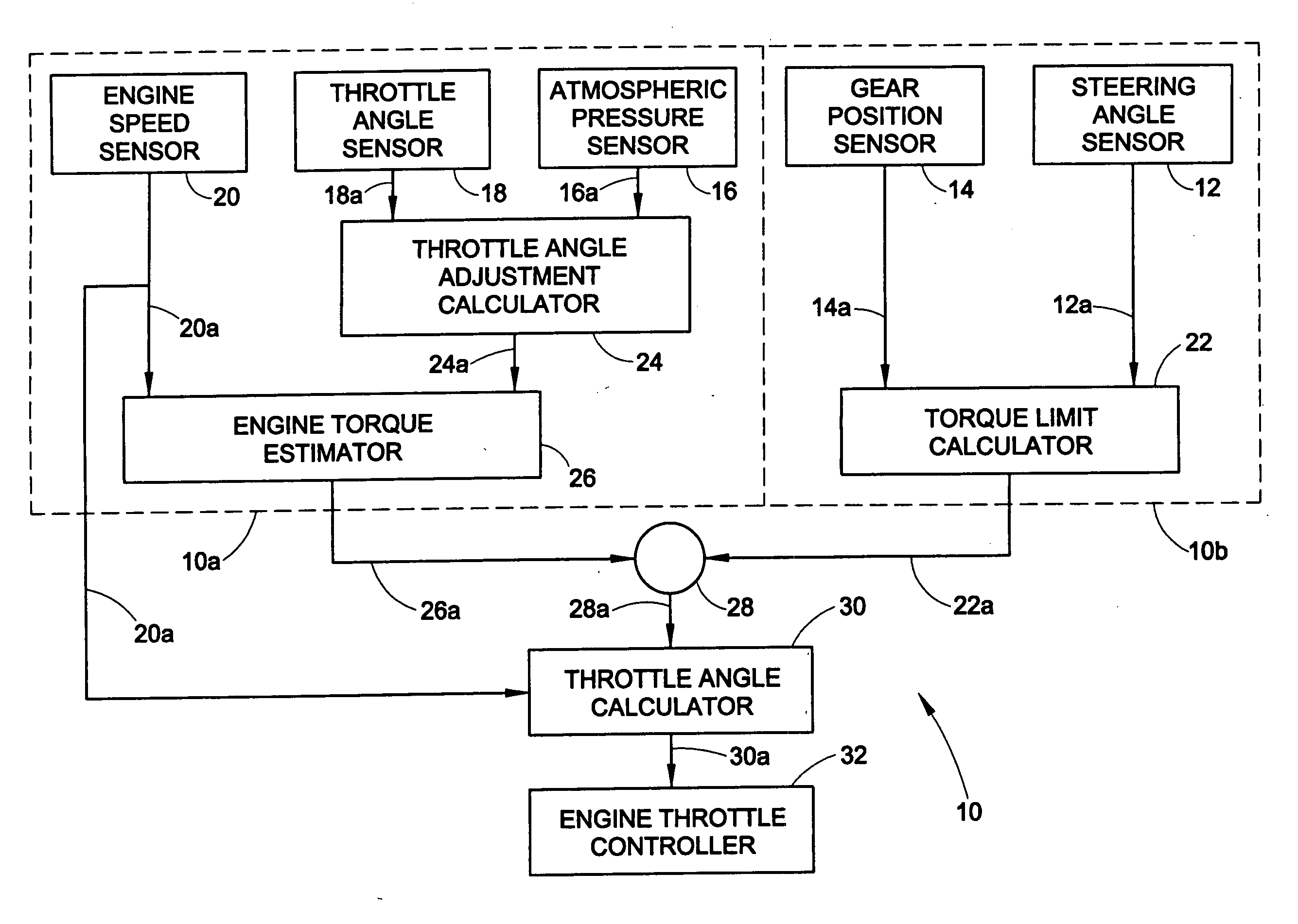
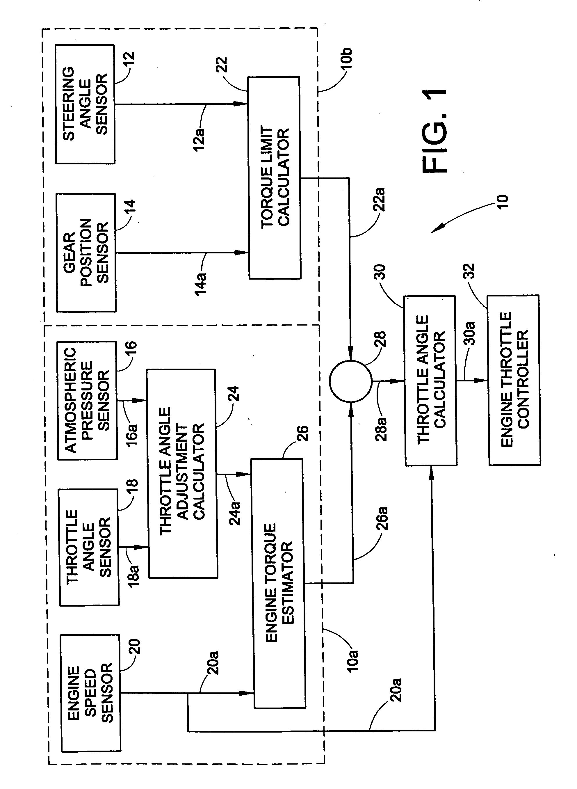
[0017] With reference to FIG. 1, the system 10 according to the present invention includes a steering angle sensor 12, a gear position sensor 14, an atmospheric pressure sensor 16, a throttle angle sensor 18, an engine speed sensor 20, a torque limit calculator 22, a throttle adjustment angle adjustment calculator 24, an engine torque estimator 26, a comparator / selector 28, a throttle angle calculator 30, and an engine throttle controller 32. As will be appreciated from the following description, the engine speed sensor 20, throttle angle sensor 18, atmospheric pressure sensor 16, throttle angle adjustment calculator 24, and engine torque estimator 26 define an estimated engine torque portion 10a of the system 10, whereas the gear position sensor 14, steering angle position sensor 12, and torque limit calculator 22 define a maximum calculated torque portion 10b section of the system 10.

[0018] The steering angle sensor 12 measures steering angle. Steering angle can, but need not be,...


PUM


Abstract

A method and system for inhibiting torque steer in a vehicle equipped with steerable wheels that are power driven. The method determines a maximum engine torque limit, determines an estimated driver-desired torque, and controls the actual torque, by adjustment of the throttle angle, to be the smaller of the maximum engine torque limit and the estimated driver-desired torque. Sensors measure steering angle and transmission gear position and a calculator determines the maximum engine torque limit based upon the steering angle and transmission gear position. Further sensors measure engine speed, throttle angle, and atmospheric pressure, and a calculator estimates driver-desired torque based upon the measured engine speed, throttle angle, and atmospheric pressure. A comparator selects the lower of the maximum engine torque limit and the driver-desired engine torque and uses the selected torque to control throttle angle to inhibit torque steer.

Description

PRIORITY CLAIM [0001] This application is a continuation of currently pending U.S. application Ser. No. 10 / 436,409 filed on May 12, 2003.BACKGROUND OF THE INVENTION [0002] 1. Field of the Invention [0003] The present invention is generally directed toward a method and system for inhibiting torque steer in a vehicle equipped with steerable wheels that are power driven. [0004] 2. Description of Related Art [0005] Vehicles equipped with steerable wheels that are power driven such as front-wheel drive vehicles and four-wheel drive vehicles have the potential to generate a difference in left / right side tire longitudinal force under the application of engine torque. This difference in left / right side tire longitudinal force can be observed in most vehicles, but is especially noticeable in vehicles equipped with a traction enhancement device such as a limited slip differential or another type of torque splitting control device. The mismatch in left / right driving torque creates a difference...

Claims


Application Information

Patent Timeline
Patent Type & Authority Applications(United States)
IPC IPC(8): F02D41/02G05D1/00G06F7/00G06F17/00
CPCF02D41/021F02D2250/26F02D2250/18F02D41/0225
Inventor POST, JAMES W. IIKLAUS, THEODORE
Owner HONDA MOTOR CO LTD
Why Eureka
Try Eureka