Clamping device for electrical cables

a technology of electrical cables and clamping devices, which is applied in the direction of kitchen equipment, domestic applications, and stands/trestles, etc., can solve the problems of increasing the temperature and affecting the operation of the clamping devi

Inactive Publication Date: 2014-12-02
LU BO
View PDF7 Cites 3 Cited by
  • Summary
  • Abstract
  • Description
  • Claims
  • Application Information

AI Technical Summary

Benefits of technology

[0009]An objective of the present invention is to provide a clamping device which is for use on outdoor overhead electrical cables and is configured to optimally compensate the adverse effect brought by thermal expansion of the electrical cables.
[0010]Another objective of the present invention is to provide a clamping device which is for use on outdoor overhead electrical cables, and is capable of apprising a relevant technician as to when the electrical cables are securely tightened so as to prevent damage on the electrical cables.
[0011]Another objective of the present invention is to provide a clamping device which is for use on outdoor overhead electrical cables, and is capable of reducing the manufacturing and maintenance cost of the overhead electrical cables. The clamping device of the present invention is simple in structure, but is capable of achieving unexpectedly good performance.
[0015]a connecting arrangement providing on the first clamping member and the second clamping member and being configured to exert a clamping force between the first clamping member and the second clamping member for securely clamping the electrical cable between the first clamping member and the second clamping member, in such a manner that when the electrical cable slightly deforms due to thermal expansion and contraction, the first clamping member and the second clamping member are arranged to move with respect to each other so as to allow a slight relative movement between the first clamping member and the second clamping member for preventing unwanted damage to the electrical cable.

Problems solved by technology

There are several disadvantages in association with the above-mentioned clamping device.
However, when weather condition changes, the electrical cables 3P are subject to thermal expansion.
When the stress is not properly released or compensated, it may damage the electrical cables 3P or the clamping device.
When this happens, the general resistance of the electrical cables 3P may increase and this may increase the temperature of the clamping device.
Since the electrical cables 3P are normally supported overhead, it is very arduous for technicians to replace the damaged cables or the damaged clamping devices.
However, when the electrical cables 3P are tightened too strongly, the electrical cables 3P may be damaged, especially when they are subject to thermal expansion as mentioned above.

Method used


Image

  • Clamping device for electrical cables
  • Clamping device for electrical cables
  • Clamping device for electrical cables

Examples


Embodiment Construction

[0021]The following detailed description of the preferred embodiment is the preferred mode of carrying out the invention. The description is not to be taken in any limiting sense. It is presented for the purpose of illustrating the general principles of the present invention. Each of the inventive features described below can be used independently of one another or in combination with other features.

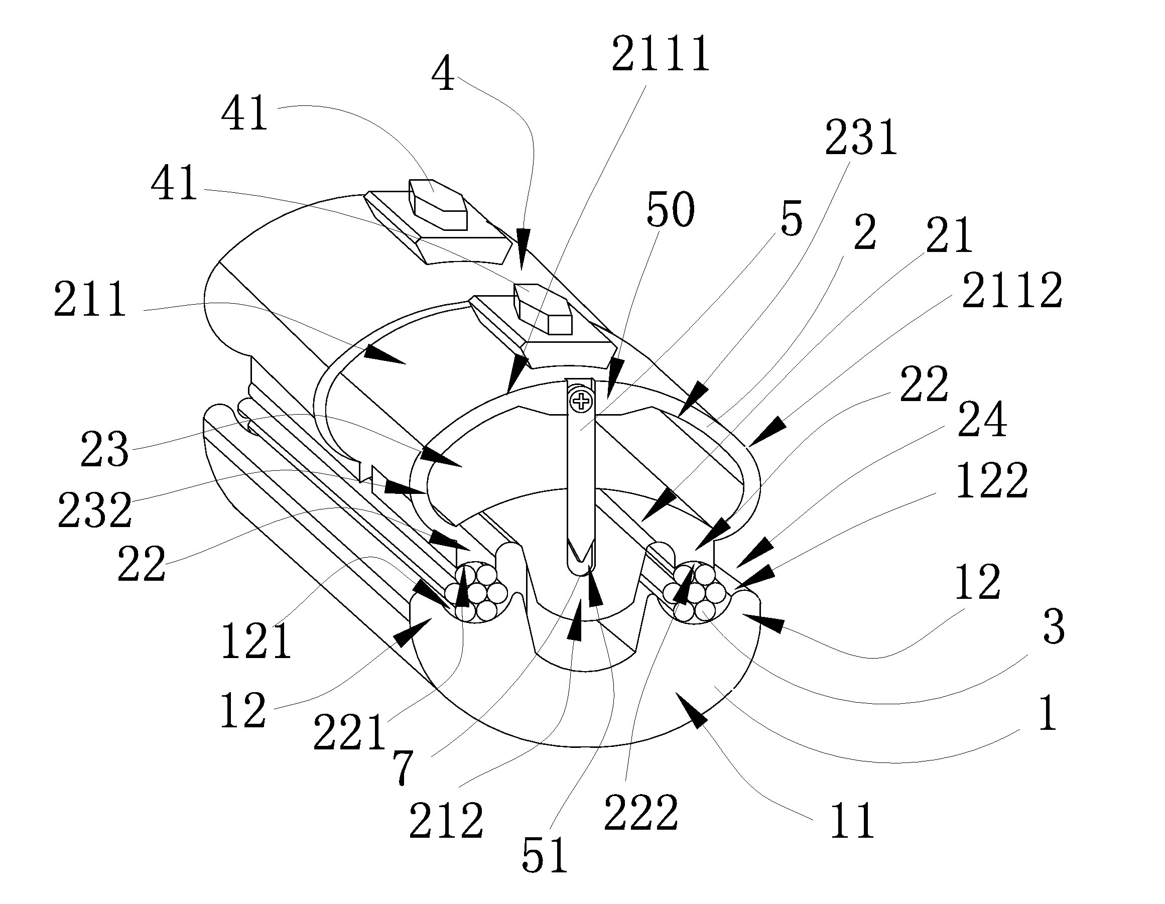
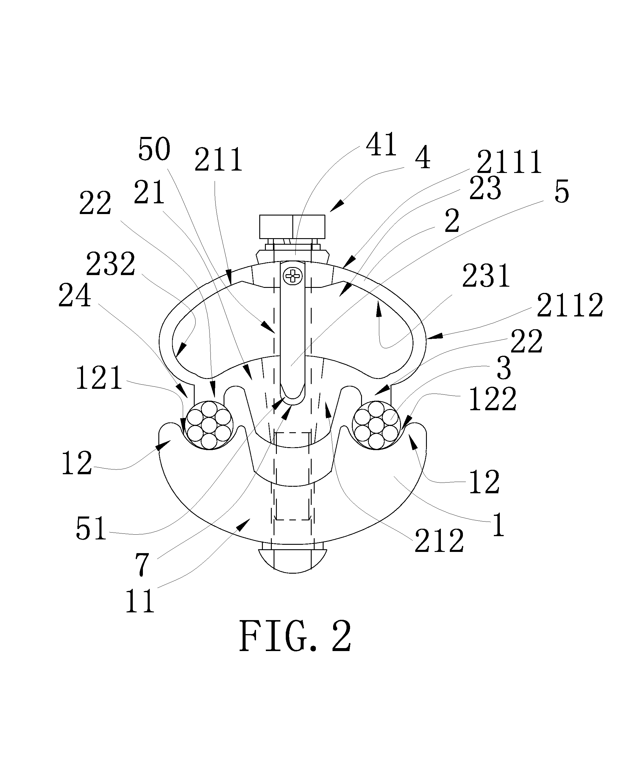
[0022]Referring to FIG. 2 to FIG. 5 of the drawings, a clamping device according to a preferred embodiment of the present invention is illustrated. The clamping device is for holding at least one electrical cable 3 which may comprise a plurality of electrical wires. Broadly, the clamping device comprises a first clamping member 1, a second clamping member 2 configured to have a predetermined elasticity or resilient ability, and a connecting arrangement 4.

[0023]The connecting arrangement 4 is provided on the first clamping member 1 and the second clamping member 2, and is configured to ex...


PUM


Abstract

A clamping device includes a first clamping member, a second clamping member, and a connecting arrangement providing on the first clamping member and the second clamping member. The connecting arrangement is configured to exert a clamping force between the first clamping member and the second clamping member, in such a manner that when the electrical cable slightly deforms due to thermal expansion and contraction, the first clamping member and the second clamping member are arranged to move with respect to each other so as to allow a slight relative movement between the first clamping member and the second clamping member for preventing unwanted damage to the electrical cable.

Description

CROSS REFERENCE OF RELATED APPLICATION[0001]This is a non-provisional application claiming the benefit of priority to a foreign application number 201210539062.0 with a filing date of Dec. 12, 2012 in China. The content of this specification is incorporated herein by reference.BACKGROUND OF THE PRESENT INVENTION[0002]1. Field of Invention[0003]The present invention relates to a clamping device, and more particularly to a clamping device which is for use on outdoor overhead electrical cables and is configured to optimally compensate the adverse effect brought by thermal expansion of the cables.[0004]2. Description of Related Arts[0005]Referring to FIG. 1 of the drawings, a conventional clamping device, such as a clamping device for overhead high voltage electrical cables 3P, usually comprises a first clamping member 9P having a plurality of first clamping arms 91P, a second clamping member 10P having a plurality of second clamping arms 100P, and a connecting device 4P providing on th...

Claims


Application Information

Patent Timeline
Patent Type & Authority Patents(United States)
IPC IPC(8): F16L3/10F16L3/22
CPCH02G3/32F16L3/105
Inventor LU, BO
Owner LU BO
Why Eureka
Try Eureka