USB connector assembly

a technology of usb connectors and connector assemblies, applied in the direction of coupling devices, two-part coupling devices, electrical devices, etc., can solve the problems of inferior conductivity effect and considerable time-consuming in the usb connector manufacturing process, and achieve the effect of avoiding any damage to the pin structur

Inactive Publication Date: 2014-12-02
ZK TEK TECH
View PDF5 Cites 2 Cited by
  • Summary
  • Abstract
  • Description
  • Claims
  • Application Information

AI Technical Summary

Benefits of technology

[0007]The primary object of the present invention is to provide a USB connector assembly, comprising a base, a main structure and a plural of pins, wherein the main structure is configured over the base which is laid with a plural of conducting pads on the top surface, and one side of those said pins are configured as bending ends which extend outside of the main structure and provide electric contact with those conducting pads correspondingly, and the main structure is configured with pin rabbets to have one side accommodate pins therein, and is characterized that the front side of the main structure is configured as a front stopper which is capable of holding against the base to maintain a firm assembly and prevent the bending ends of the pins from raising up and a loose contact with the conducting pads. Therefore, the present invention can practically avoid any damage to the pins structure due to plug-in or pull-out.
[0008]Another object of the present invention is to provide a USB connector assembly, wherein both lower corners of the front stopper are further extended backward as a clipping arm respectively to have a tight clip-on connection with the front end of base, and the upper end of the front stopper is configured as a sloping edge to enhance a smooth contact while plug-in or pull-out. Thus, the present invention provides a better and simple joint structure.
[0009]And, one more object of the present invention is to provide a USB connector structure, wherein the bottom side of the fixing structure is further configured with a step rabbet which provides a pushing effect toward pins to avoid raising up and accommodates those pins extended outside the main structure to enable the curve part of each bending edge having a tight and better electric contact with those conducting pads laid on the base correspondingly. This joint structure can provide a useful structural combination without traditional soldering procedure and quick assembly efficiency for the manufacturer, but also enhance the transmission function and safety for the ordinary USB interface user.
[0010]By above-mentioned description, the present invention, comprising a base, a main structure and a plural of pins, is characterized that the front side of the main structure is configured as a front stopper which is capable of holding against the base to maintain a firm assembly and prevent the bending ends of the pins from raising up and a loose contact with the conducting pads, and enables a USB connector structure with a more efficient manufacturing process and a more reliable hardware structure. Besides, the present invention is assembled free from soldering process which provides a convenient and efficient method to shorten prior USB connector manufacturing process.

Problems solved by technology

The soldering procedure takes a considerable time consuming during the USB connector manufacturing.
If the pins' assembly are not soldered on the base, the bending ends tends to raise up and lead to an inferior conducting effect after many times plug-in and pull-out or even cause unexpected damage in data transmission.

Method used


Image

  • USB connector assembly
  • USB connector assembly
  • USB connector assembly

Examples


Embodiment Construction

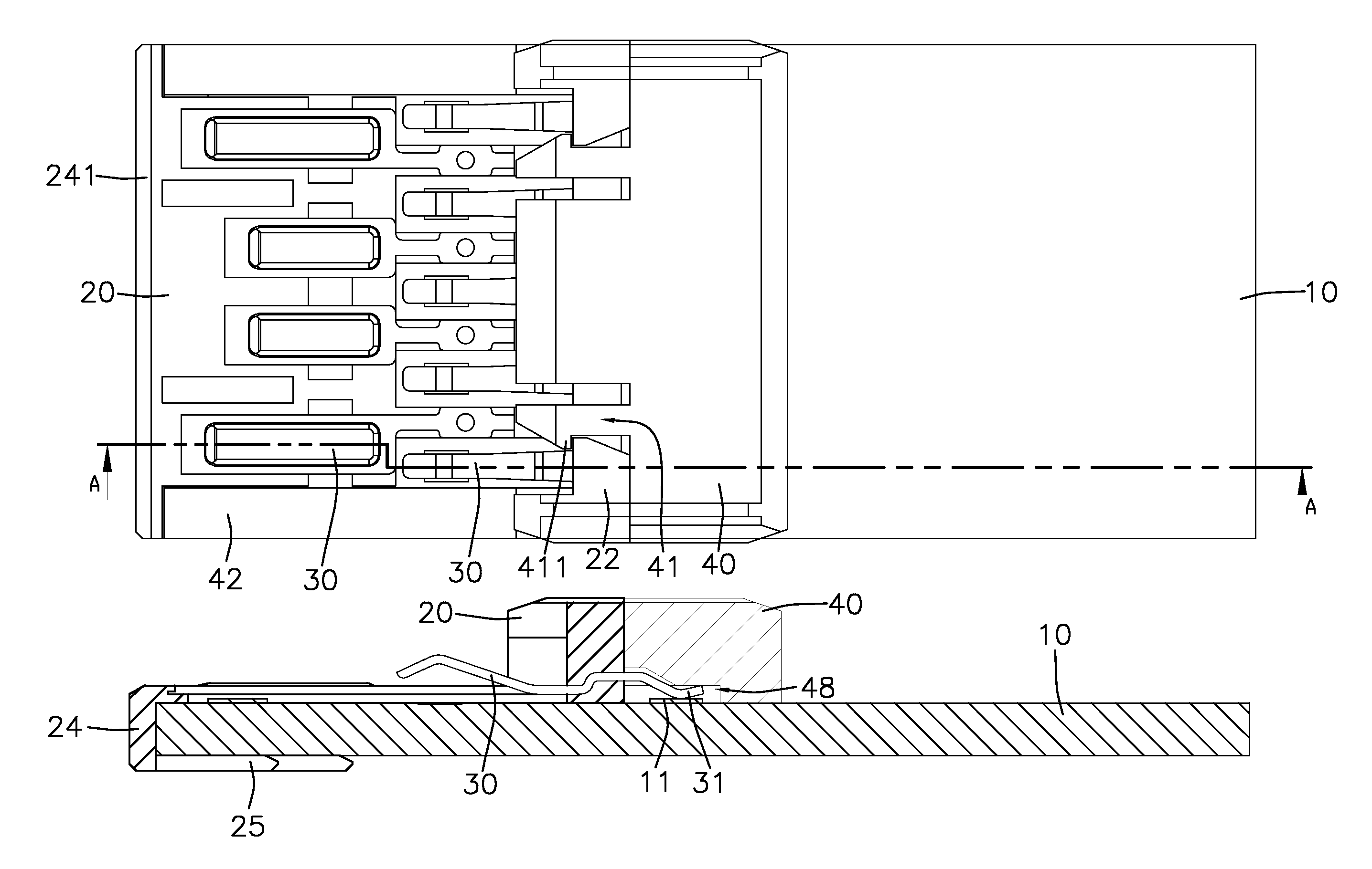
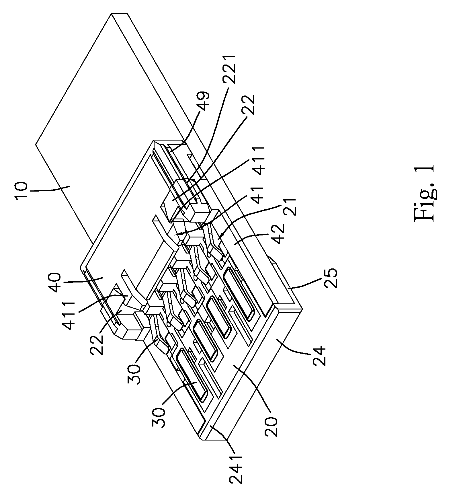
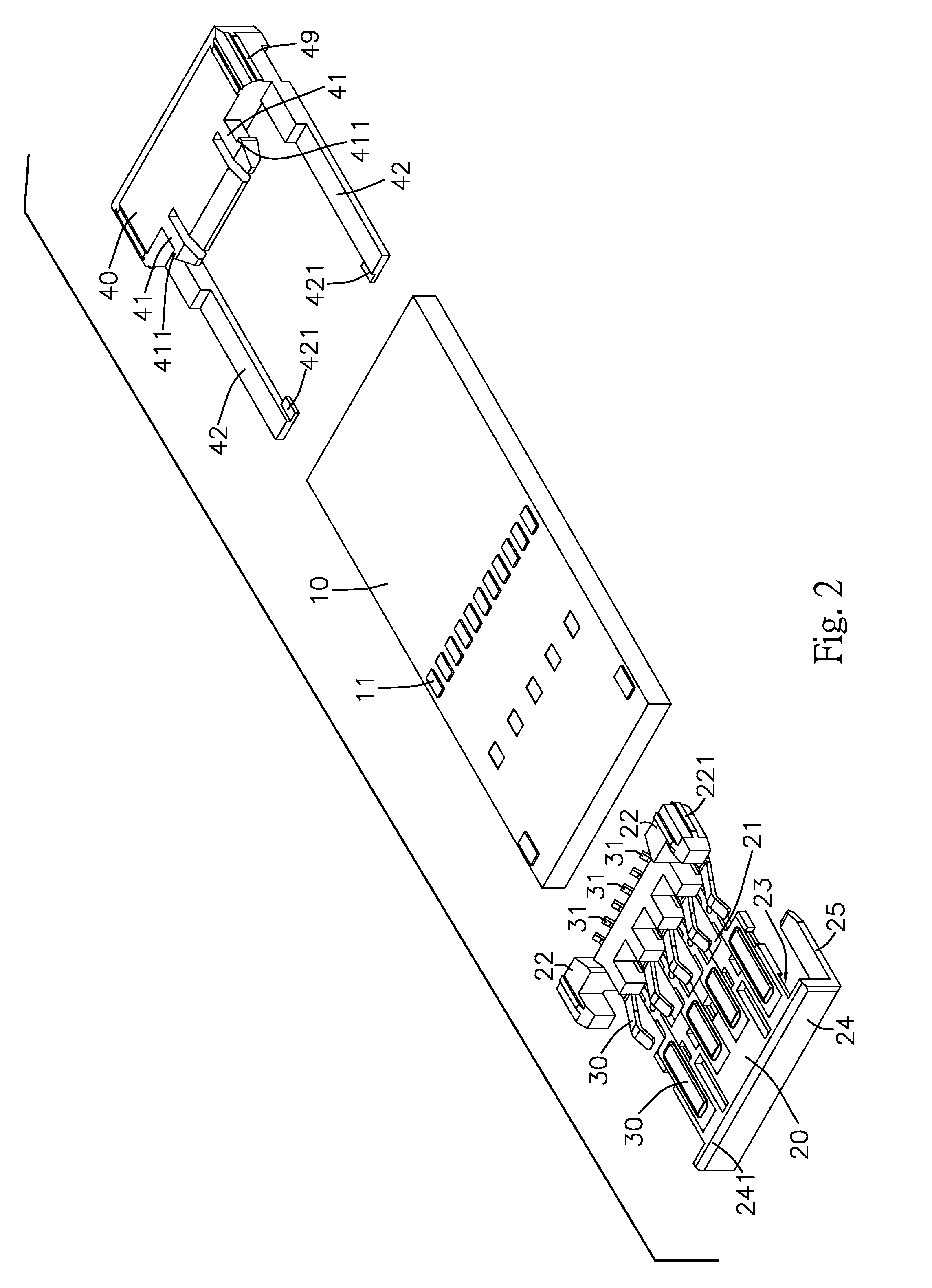
[0022]Referring to FIGS. 1 to 7, the present invention relates to a USB connector assembly and comprises a base 10, a main structure 20 and a plural of pins 30, wherein the main structure 20 is configured over the base 10 which is laid with a plural of conducting pads 11 on the top surface, and one side of those said pins 30 are configured as bending ends 31 which extend outside of the main structure 20 and provide electric contact with those conducting pads 11 correspondingly, and the main structure 20 is configured with pin rabbets 21 (as shown in FIGS. 1 and 2) to have one side accommodate pins 30 therein, and is characterized that the front side of the main structure 20 is configured with a front stopper 24 which is capable of holding against the base 10, and both lower corners of the front stopper 24 are further extended backward as a clipping arm 25 (as shown in FIG. 1) respectively to have a tight clip-on connection with the front end of base 10.

[0023]Meanwhile, the upper end...


PUM


Abstract

A USB connector assembly, configured with a combination structure of a base, a main structure and a plural of pins, to prevent the bending ends of the pins from a loose contact with the conducting pads due to the combination of main structure configured over the base. And, the present invention can be applied in various USB connectors or similar connecting structure.

Description

BACKGROUND OF THE INVENTION[0001]1. Field of the Invention[0002]The present invention relates to a USB connector assembly, comprising a base, a main structure and a plural of pins, wherein the main structure is configured over the base and a plural of conducting pads are laid on the base, the main structure is configured with pin rabbets to have one side accommodate pins therein, and is characterized that a front stopper is extended forward of the main structure and is capable of holding against the base to maintain a firm assembly and prevent the bending ends of the pins from a loose contact with the conducting pads. Therefore, the present invention can practically avoid any damage to the pins structure due to plug-in or pull-out and it enables a more smooth and efficient application in the USB connector.[0003]2. Description of Prior Art[0004]The USB connectors had been adopted as a standard port to act as a transmission interface between the computer and external peripherals. Espe...

Claims


Application Information

Patent Timeline
Patent Type & Authority Patents(United States)
IPC IPC(8): H01R24/00H01R24/64
CPCH01R13/506H01R24/62H01R12/714H01R13/6658H01R24/64
Inventor CHAN, YI CHIA
Owner ZK TEK TECH
Why Eureka
Try Eureka