
Method and apparatus for lighting

a technology of led light source and lighting apparatus, which is applied in the direction of lighting and heating apparatus, lighting support devices, fixed installations, etc., can solve the problems of waste and significant over-the-minimal level of illumination, and achieve the effect of reducing the amount of fixtures, reducing capital equipment costs, installation costs and maintenance costs

Inactive Publication Date: 2014-12-09
SET INDS CORP
View PDF23 Cites 30 Cited by
  • Summary
  • Abstract
  • Description
  • Claims
  • Application Information

AI Technical Summary

Benefits of technology

The invention aims to address three sets of objectives for standard indirect lighting fixtures. Firstly, it seeks to improve the distribution of light in a space. Secondly, it looks to address the limitations of conventional indirect lighting. Finally, it looks to expand the capabilities and features of indirect lighting. The invention suggests using a large field of illumination to reduce the number of fixtures needed. Increasing the spacing between fixtures also reduces energy costs and maintenance costs. The invention also aims to reduce or eliminate self-illumination of the fixture, making it dark when on. Overall, the invention offers a more efficient and effective solution for lighting large spaces while minimizing costs and maximizing flexibility.

Problems solved by technology

From a strictly energy conscious point of view, any illumination levels that are significantly above the minimum level are wasteful.

Method used


Image

  • Method and apparatus for lighting
  • Method and apparatus for lighting
  • Method and apparatus for lighting

Examples


Embodiment Construction

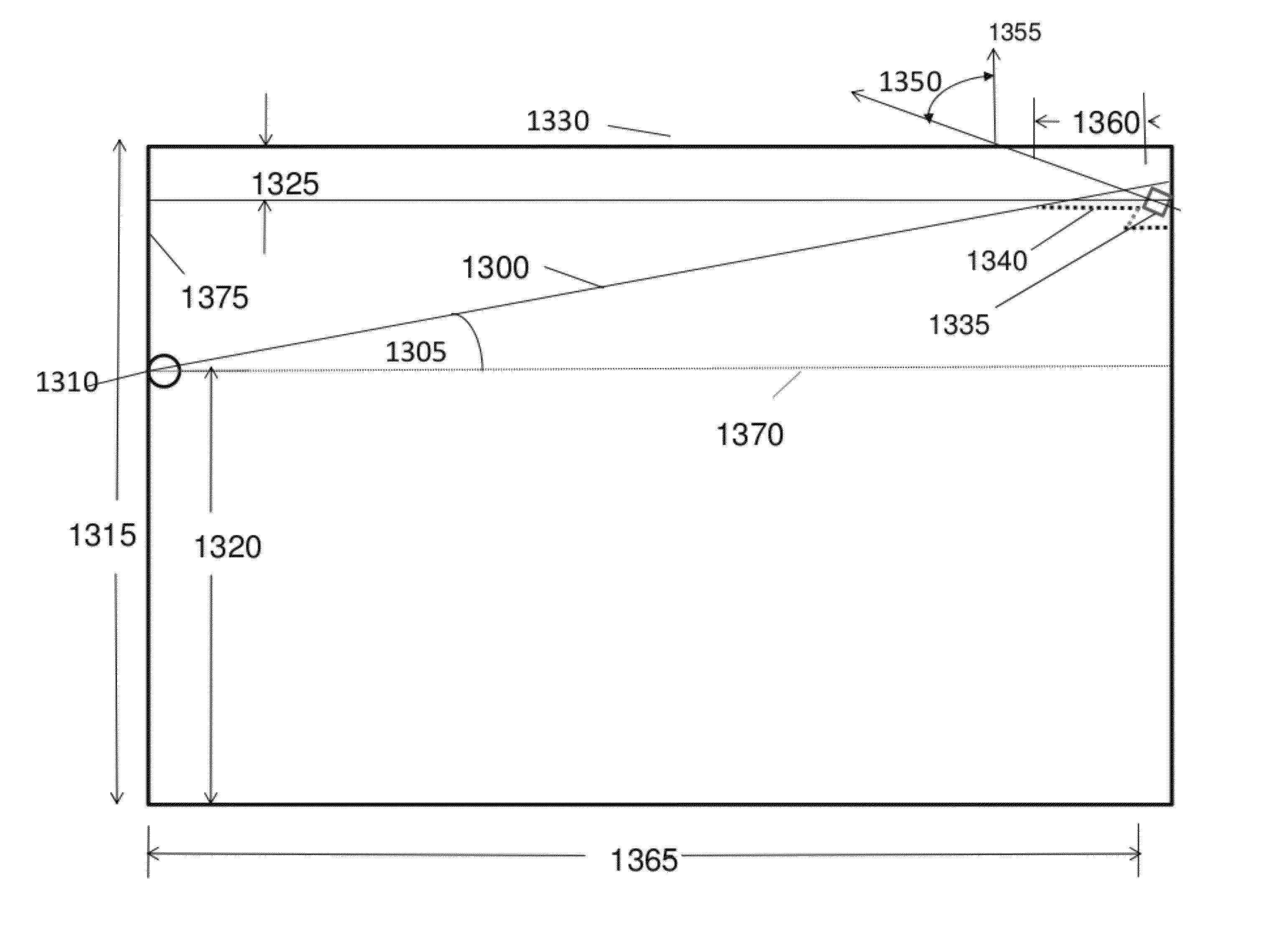
[0071]For the purposes of differentiating between conventional, or prior art, indirect lighting OPDSs and the indirect OPDSs contemplated in embodiments of the invention, the following features of OPDSs are highlighted: (1) the angular distribution of light from the light fixtures relative to the ceiling, and (2) the means for obscuring or blocking the direct view of those light sources or any interior fixture surfaces with high brightness.

[0072]Optical Angular Distribution

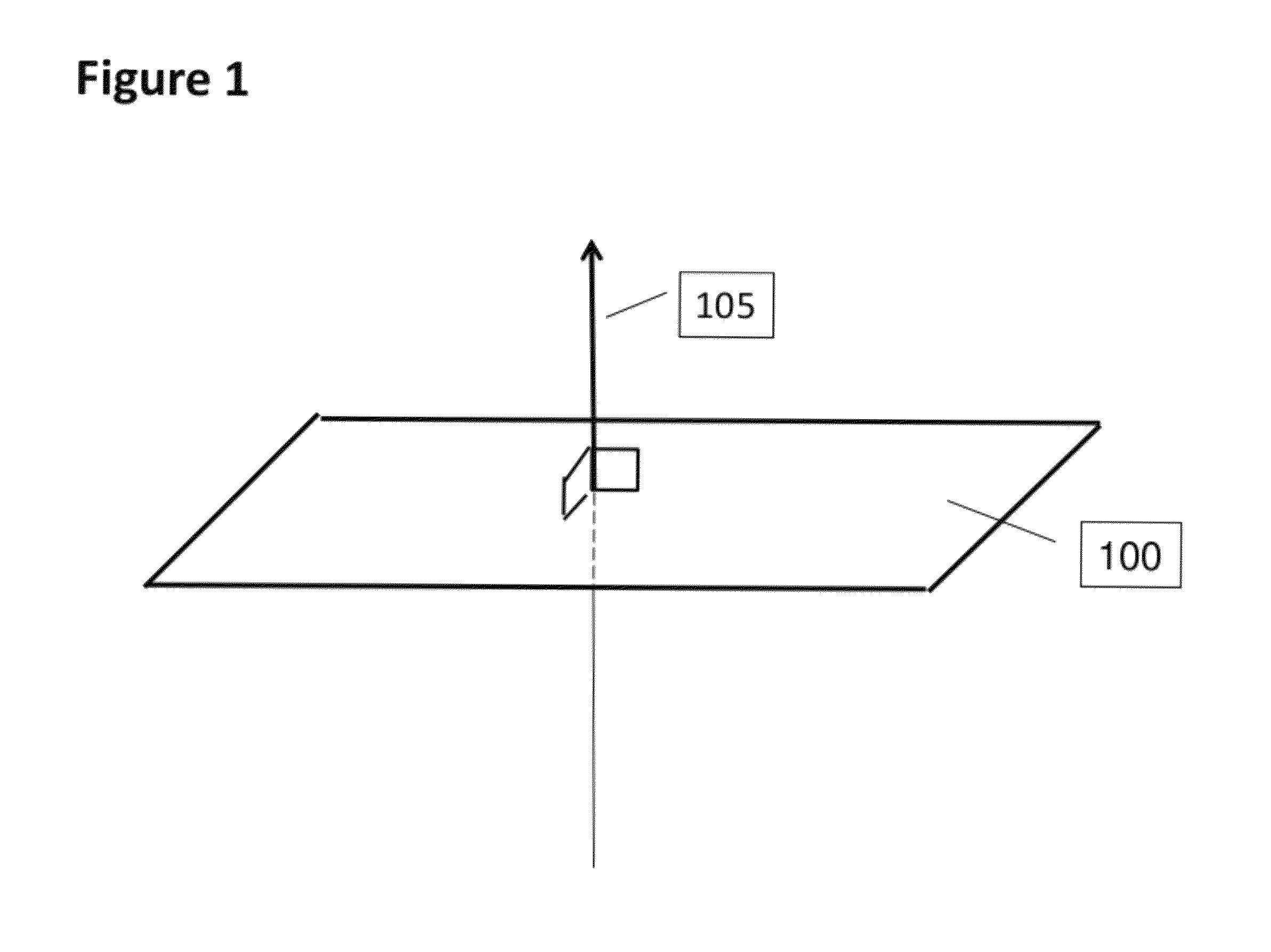
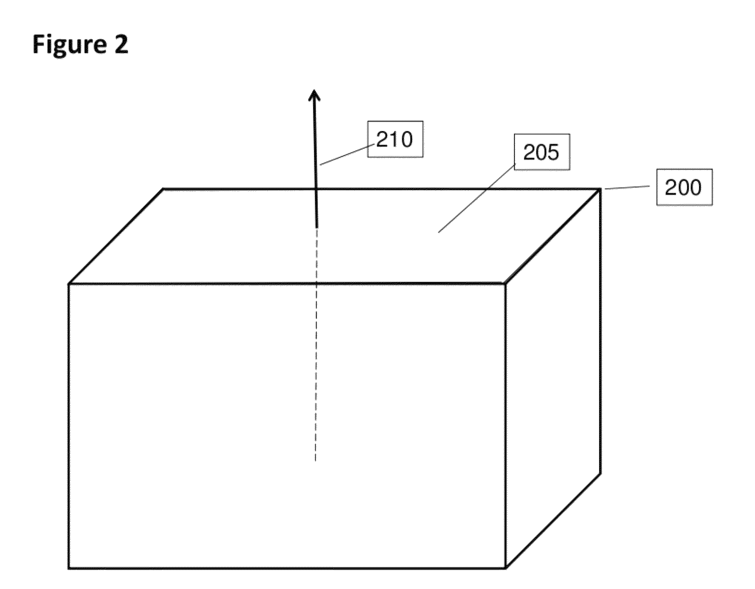
[0073]The ceiling's normal vector is defined as the vector that is perpendicular to all lines tangent to the plane. FIG. 1 illustrates the simplest case in which the ceiling surface is a plane 100 with a vector 105 normal to the surface of the plane. A planar surface is particularly important because most rooms 200 have a ceiling 205 which is a plane and an associated normal vector 210, as shown in FIG. 2. Now consider FIG. 3 showing the prior art where a conventional indirect light fixture 305 is hanging from the...


PUM


Abstract

A lighting fixture includes a directional light source that produces a plurality of light rays. An optical module is coupled to the directional light source to focus the plurality of light rays into a beam of light rays to be output by the lighting fixture. The angular distribution of a majority of the beam relative to a vector normal to a ceiling on or near which the fixture is to be installed is in a range of 70 to 95 degrees. A blocking structure is used to block a direct view of the beam of light when the fixture is installed such that only indirect light is primarily visible from a viewer at least in or around a working plane substantially parallel to the ceiling.

Description

RELATED APPLICATIONS[0001]This application claims priority to U.S. provisional patent application No. 61 / 393,801 filed Oct. 15, 2010.FIELD OF THE INVENTION[0002]Embodiments of the invention relate to methods and apparatuses utilizing LED light sources however it is recognized that other directional sources could be used instead. Directional light sources are sources characterized by the ability of an optical system to groom the emitted light into a beam. For example a laser is a directional source. Another example is a waveguide that is coupled to a remote source. Yet another example of a LED light source that is used to make a beam is the arc lamp used in projectors.BACKGROUND OF THE INVENTIONDefinitions[0003]CILF: Conventional Indirect Lighting Fixture as used in the prior art.[0004]Coefficient of Utilization: The ratio of the integrated light power at the working plane to the total light power emitted by the fixtures.[0005]IES: Illuminating Engineering Society.[0006]LED: Light Em...

Claims


Application Information

Patent Timeline
Patent Type & Authority Patents(United States)
IPC IPC(8): F21Y101/02F21S8/04F21V7/00F21S8/00
CPCF21Y2101/02F21V7/0008F21S8/04F21Y2115/10
Inventor THOMAS, MARK S.CROSS, WILLIAM C.
Owner SET INDS CORP
Learn More