Timepiece with coupled oscillators in chronograph mode

a technology of coupled oscillators and timepieces, which is applied in the direction of frequency stabilisation mechanisms, instruments, and timepieces that are very shock sensitive or high energy consumers, and can solve the problems of high energy consumption, high cost, and dubious quality of timepieces, so as to reduce energy consumption and minimum drift, the effect of improving resolution

Active Publication Date: 2014-12-09
THE SWATCH GRP RES & DEVELONMENT LTD
View PDF9 Cites 4 Cited by
  • Summary
  • Abstract
  • Description
  • Claims
  • Application Information

AI Technical Summary

Benefits of technology

[0005]It is an object of the present invention to overcome all or part of the aforementioned drawbacks by proposing a timepiece capable of displaying the time or measured time with a chronograph system with better resolution, while ensuring the usual robustness of a mechanical watch, reduced energy consumption and minimum drift between the time display and the measured time display, even if the measured time is greater than a minute.
[0007]It is therefore clear that, even in the event of shocks, rate variations will be minimal owing to the construction which allows the two oscillators to be synchronised. Consequently, the timepiece according to the invention is capable of displaying the time and / or the measured time with a chronograph system with better resolution and / or better precision while ensuring a high level of robustness, low power consumption and minimal drift between the time display and the measured time display, even if the measured time is greater than a minute.
[0016]the two frequencies are higher than 5 Hz for displaying both the time and the measured time with better resolution and / or better precision;
[0017]according to a second embodiment, the first frequency is higher than the second frequency so as to display the time with better resolution and / or better precision;
[0019]according to a third embodiment, the first frequency is lower than the second frequency so as to display the measured time with better resolution and / or better precision;

Problems solved by technology

However, these timepieces may be very shock sensitive or high energy consumers, which prevents them from becoming common.
However, after several seconds, it is observed that the seconds display of the two oscillators is no longer the same, which may make the quality of the timepiece appear dubious.

Method used


Image

  • Timepiece with coupled oscillators in chronograph mode
  • Timepiece with coupled oscillators in chronograph mode
  • Timepiece with coupled oscillators in chronograph mode

Examples


first embodiment

[0031]Depending upon the desired application of the timepiece, the first f1 and second f2 frequencies may or may not be identical. Thus, in a first embodiment, the first and second frequencies f1, f2 are identical and preferably higher than 5 Hz so as to display both the time and the measured time with better resolution and / or better precision. In this embodiment, frequencies f1, f2 may, for example, be equal to 10 Hz or 50 Hz for displaying 1 / 20th or 1 / 100th of a second respectively.

[0032]In a second embodiment, the first frequency f1 is higher than the second frequency f2 so as to display the time with better resolution and / or better precision. In a similar manner to the first embodiment, the first frequency f1 is at least equal to 10 Hz and the second frequency f2 is preferably comprised between 1 and 5 Hz. Indeed, by way of example, it may be desired for the measured time seconds to be incremented by a single step per second, i.e. second frequency f2 is equal to 1 Hz, “like” a q...

third embodiment

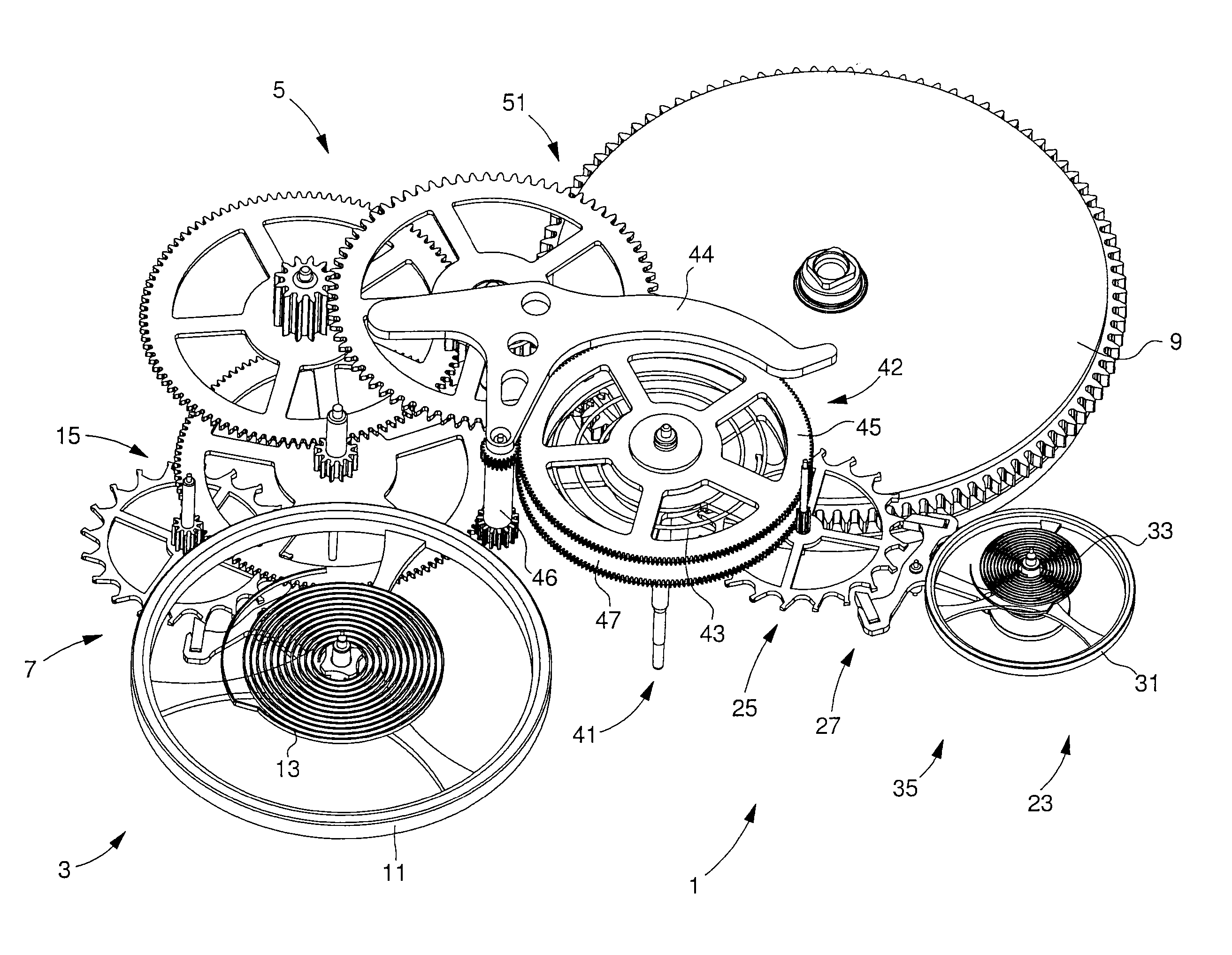
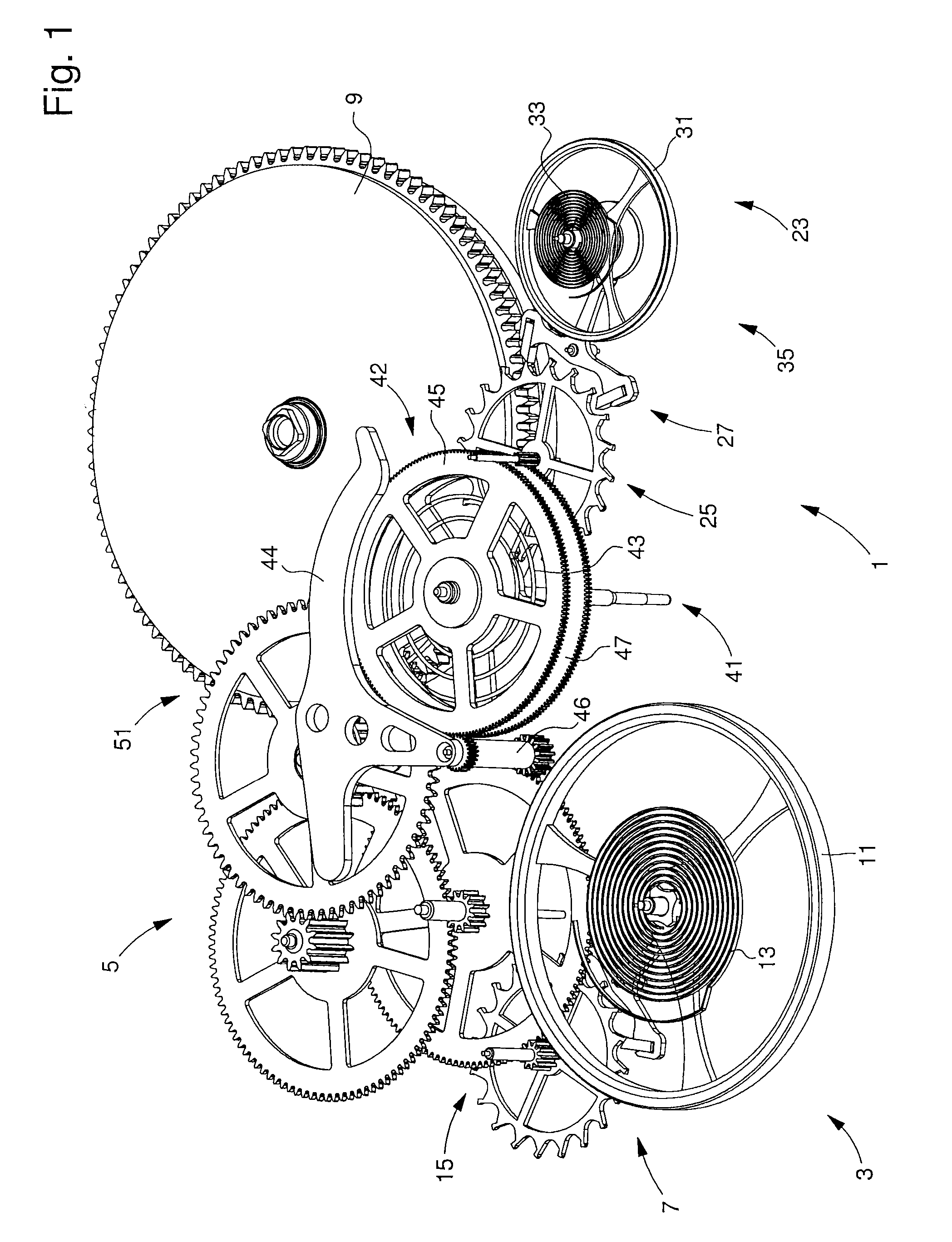
[0034]Simulations were developed hereinafter to describe the synchronisation between these two oscillators 15 and 35. The third embodiment has been arbitrarily selected for the explanation. Thus, oscillator 15 is selected to be a low frequency oscillator and is called the first oscillator. Consequently, in the example below, the second oscillator will be high frequency oscillator 35, which will be synchronised with low frequency oscillator 15.

[0035]Preferably according to the invention, the second oscillator 35 is selected with a strong anisochronism according to amplitude, described by the anisochronism slope Γ, and the amplitude A02 at which the rate is zero. Moreover, it is assumed that first oscillator 15 always has a substantially zero rate by slightly varying its amplitude.

[0036]The simulations show the change in the two oscillators 15, 35, i.e. their amplitude and state of phase difference with time, and thus mean that it can be checked whether or not it is possible to synchr...


PUM


Abstract

A timepiece includes a first oscillator oscillating at a first frequency and connected by a first gear train to an energy source to display the time. The timepiece also includes a chronograph system including a second gear train connected to the first gear train via a coupling device for selectively measuring a time. The chronograph system further includes a second oscillator, which is connected to the second gear train and oscillates at a second frequency. Moreover, the second gear train is connected to the first gear train by an elastic coupling, in order to synchronize the rate of the two oscillators using the same energy source when the coupling device is in a coupled position.

Description

[0001]This application claims priority from European Patent Application No. 11181505.6 filed Sep. 15, 2011, the entire disclosure of which is incorporated herein by reference.FIELD OF THE INVENTION[0002]The invention relates to a timepiece with coupled oscillators in chronograph mode and a timepiece of this type comprising two oscillators intended to display at least one value less than or equal to a second with better resolution and / or better precision.BACKGROUND OF THE INVENTION[0003]It is known to form timepieces with increased frequency in order to improve resolution. However, these timepieces may be very shock sensitive or high energy consumers, which prevents them from becoming common.[0004]It is therefore clear that it is easier to manufacture a calibre by mounting a low frequency oscillator, typically 4 Hz, to display the time and another high frequency oscillator, typically 10 or 50 Hz, which is independent from the first, to display a measured time with improved resolution...

Claims


Application Information

Patent Timeline
Patent Type & Authority Patents(United States)
IPC IPC(8): G04B17/00G04F7/08G04B17/26
CPCG04B17/26G04F7/08G04B17/20G04F7/0823
Inventor HELFER, JEAN-LUCHESSLER, THIERRYCONUS, THIERRY
Owner THE SWATCH GRP RES & DEVELONMENT LTD
Why Eureka
Try Eureka