Multi-hop wireless communications system and method

a wireless communication and multi-hop technology, applied in wireless communication, wireless commuication services, high-level techniques, etc., can solve the problems of inability to direct communication with the base station, low data rate, inability to respond to rapidly changing propagation conditions, etc., to achieve the effect of reducing the amplification of nois

Inactive Publication Date: 2014-12-09
RPX CLEARINGHOUSE
View PDF9 Cites 34 Cited by
  • Summary
  • Abstract
  • Description
  • Claims
  • Application Information

AI Technical Summary

Benefits of technology

[0012]The first and second aspects of the present invention enable a reduction in the signalling overhead, as compared to the use of link state protocols, because the decision as to which relay equipments carry which signals is not made centrally, for example at a base station or at an end user terminal of the system. Instead, this decision making process is distributed to the relay equipments, which each decide, which of the signals they receive from source equipments of the system to relay to a destination equipment. In addition the routing of signals via relay equipments in accordance with the present invention adapts quickly to changes in propagation conditions in the system environment.
[0018]It is advantageous, that the relay equipments select from the plurality of signals they receive from source equipments those which are of the highest quality in terms of Signal to Interference and Noise Ratio (SINR), Carrier to Interference and Noise Ratio (CINR) or received signal strength to relay to destination equipments. In this way the amplification of noise by the relay equipments is minimised. Accordingly, the or each relay equipment measures the quality of the signals it receives and selects, based on the quality of the received signals, a signal to relay. The component of the relay equipment for carrying out such measurements and for making such selections is referred to herein as a signal processor. However, it will be apparent to those skilled in the art that numerous implementations are possible, including a micro-computer or a digital signal processor, without deviating from the spirit of the invention. Thus, the relay equipments may comprise a signal processor for measuring the quality of each signal the relay equipment receives, for comparing the quality measured for each signal to a threshold quality for that signal and for rejecting those received signals of a quality below the threshold. In addition or alternatively, the signal processor may measure the quality of each signal the relay equipment receives and select the signal having the best measured quality. This may be achieved by the signal processor measuring the quality of each signal it receives, comparing the quality measured for each signal to a threshold quality for that signal, forming a candidate set of signals comprising those received signals having a quality above the threshold and selecting a signal from the candidate set of signals.
[0019]For an uplink signal transmitted from an end user terminal to a base station, via a relay equipment, the signal processor of the relay equipment may measure the quality of each signal it receives on an uplink from an end user terminal, compare the quality measured for each uplink signal to a threshold quality for that uplink signal, form a candidate set of uplink signals comprising those received uplink signals having a quality above the threshold, measure the quality of each signal it receives on a downlink from a base station, compare the quality measured for each downlink signal to a downlink threshold quality for that downlink signal, form a candidate set of downlink signals comprising those received downlink signals having a quality above their thresholds, select that uplink signal of the candidate set of uplink signals having the biggest difference between its measured quality and its threshold quality whose corresponding downlink signal is a member of the candidate set of downlink signals and then the relay equipment will relay that selected uplink signal towards the destination equipment. In this way the relay equipment chooses the best quality of signal to relay, again minimising noise amplification by the relay equipments of the system.
[0022]In order to minimise the amplification of noise by the relay equipments and favour the amplification of high quality signals by the relay equipments of the system, each relay equipment may amplify the selected signal it relays by an amount dependent on the measured quality of the selected signal. The measure of quality of a signal received by the relay equipment may be the SINR, CINR or the received signal strength of the received signal.

Problems solved by technology

Some of the end user terminals may be located unfavourably within the cell so that a direct communication with the base station is not possible, or will only support a low data rate.
Therefore, if a direct communication between a source equipment (for example, a base station or an end user terminal) and a destination equipment (for example, the other of an end user terminal or base station, respectively) is poor, an indirect communication can be made via one or more relays.
Therefore, these protocols are inherently slow and cannot respond to rapidly changing propagation conditions.
In addition whenever an optimum path changes, some link layer packets are left in buffers on the old optimum path, leading to fragmentation of higher layer packets, increased jitter and delay.
Also, although the optimum path may be adjusted in response to traffic load, there is potential for added delay at the switching relay equipments.

Method used


Image

  • Multi-hop wireless communications system and method
  • Multi-hop wireless communications system and method
  • Multi-hop wireless communications system and method

Examples


Embodiment Construction

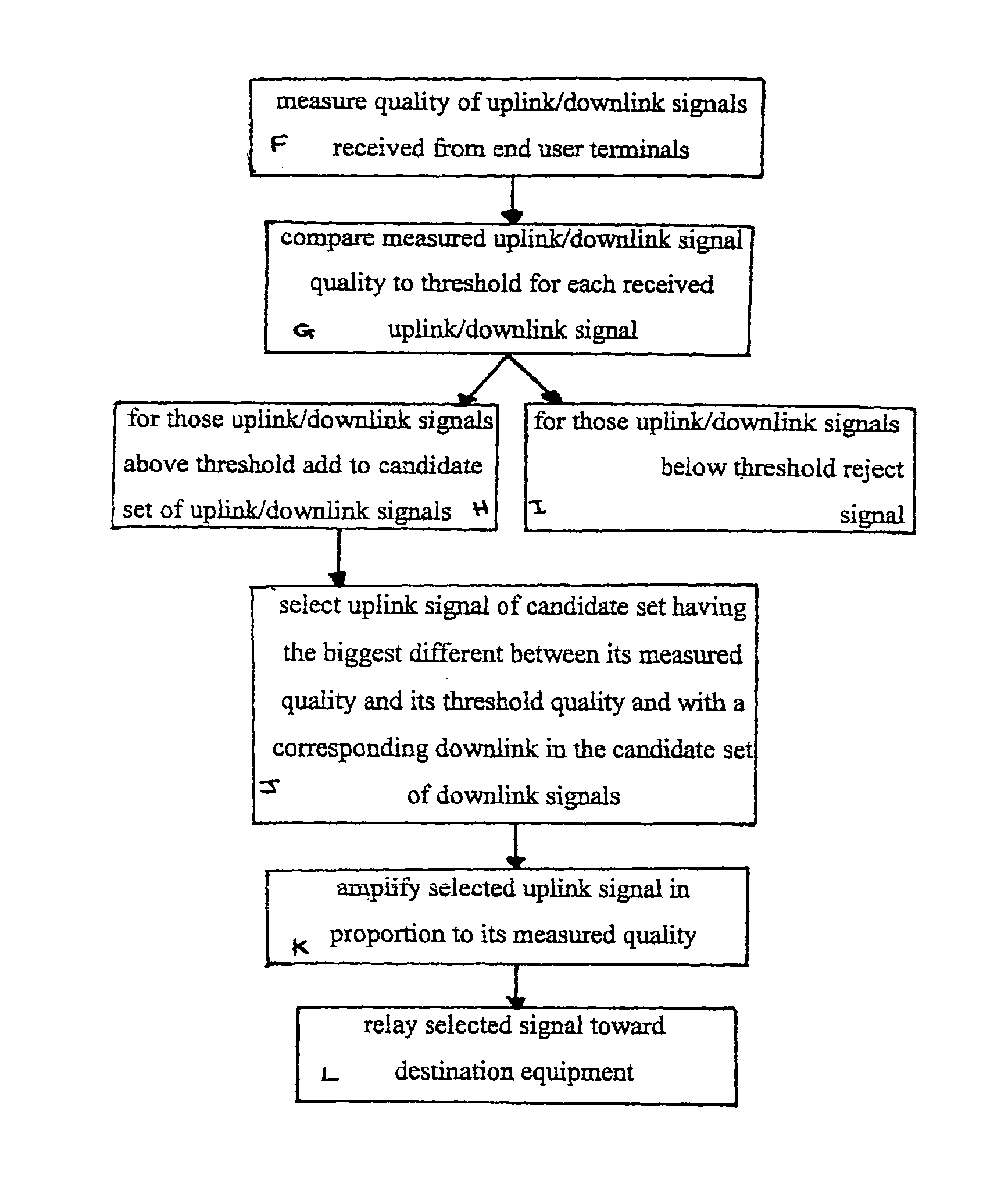
[0039]There will now be described by way of example the best mode contemplated by the inventor for carrying out the invention. In the following description, numerous specific details are set out in order to provide a complete understanding of the present invention. It will be apparent, however, to those skilled in the art that the present invention may be put into practice with variations of the specific.

[0040]One aspect of the present invention are the mechanisms by which relay equipments are chosen from the many that may be available for a communication and the way in which the communication paths between source and destination equipments, via relay equipments are set up and maintained.

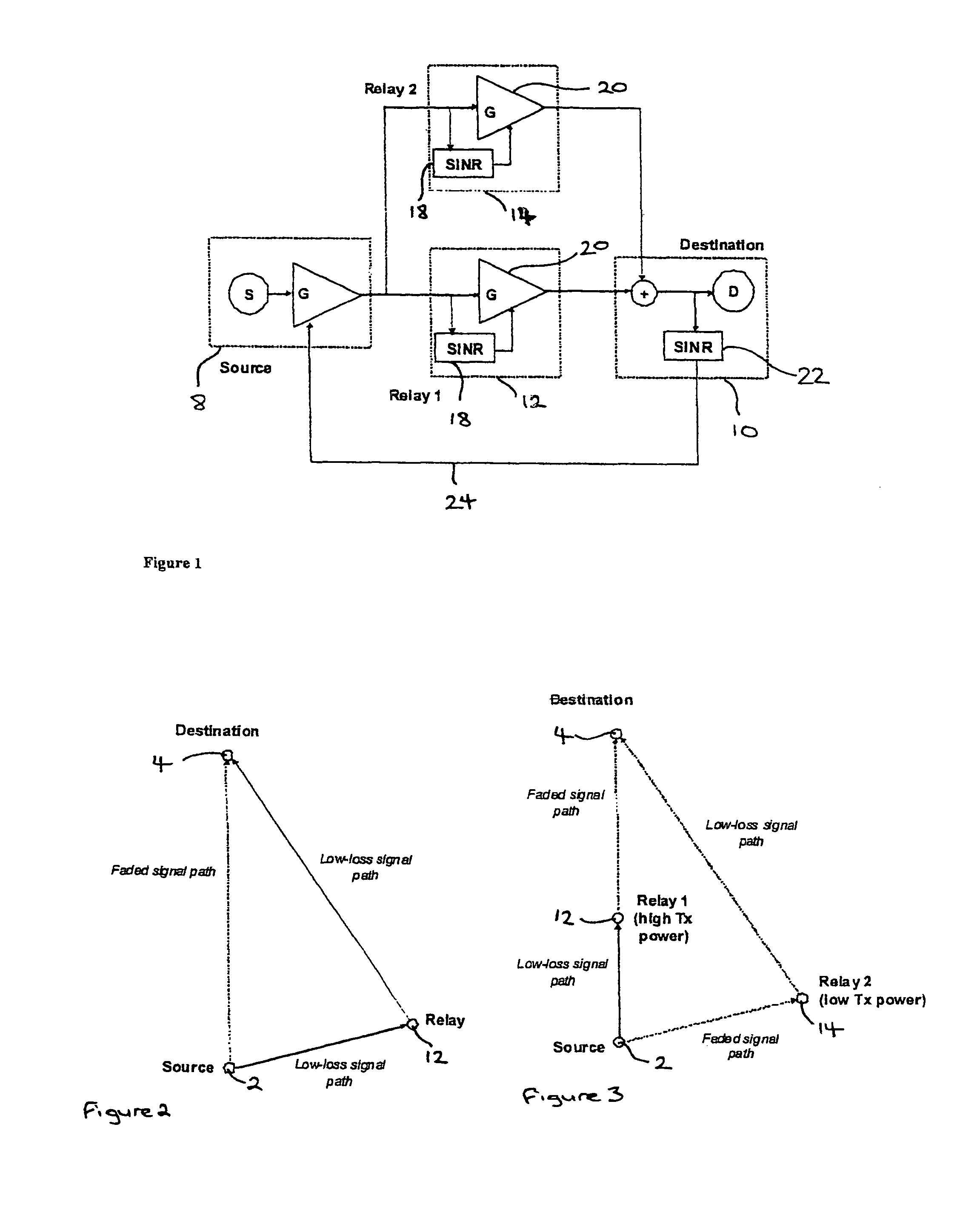
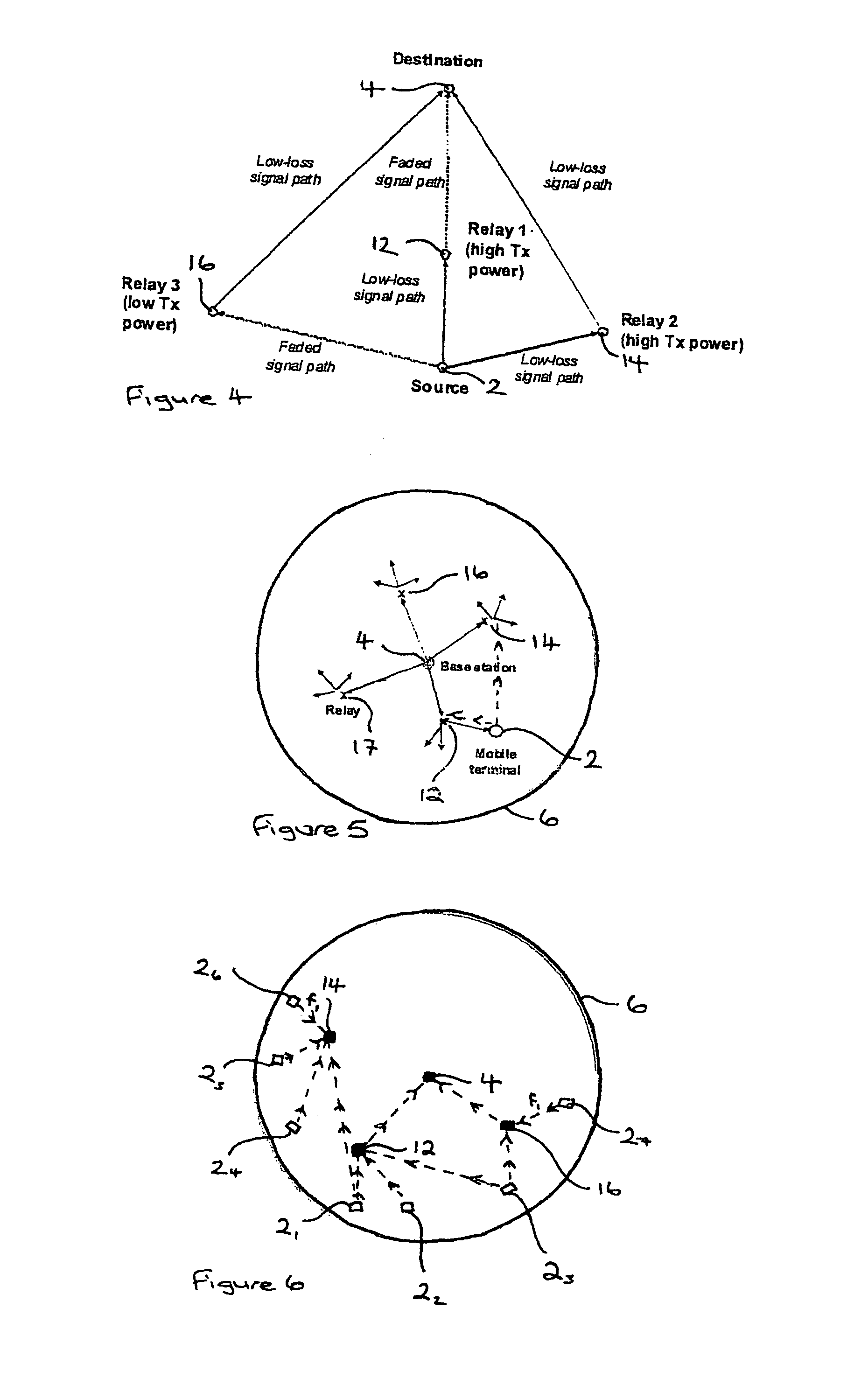
[0041]FIGS. 2 to 4 and 6 to 8 are used to describe embodiments of the present invention relating to an uplink, in which the source equipment is a mobile end user terminal (2) and the destination equipment is the base station (4) of the cell (6) in which the mobile terminal is located. The mobile ter...


PUM


Abstract

A multi-hop wireless, for example cellular, communications system is provided comprising a source equipment which may be one of a base station or an end user terminal for transmitting signals towards a destination equipment which may be the other of a base station or an end user terminal via at least one relay equipment. The relay equipment receives a plurality of signals transmitted from one or more source equipments of the system and from this plurality of signals selects a signal to relay. In this way the decision about which relays are included in which communication paths in the system is distributed to the relay equipments of the system, thus reducing the signalling overhead as compared with link state protocols which are typically used for routing in such multi-hop systems.

Description

CROSS-REFERENCE TO RELATED APPLICATION[0001]This application is a continuation-in-part of Utility patent application Ser. No. 10 / 456,249, filed Jun. 6, 2003, now U.S. Pat. No. 7,184,703, entitled MULTI-HOP WIRELESS COMMUNICATIONS SYSTEM HAVING RELAY EQUIPMENTS WHICH SELECT SIGNALS TO FORWARD.FIELD OF THE INVENTION[0002]This invention relates to a multi-hop wireless communications system, in particular a multi-hop wireless cellular communications system, in which a source equipment and a destination equipment, for example an end user terminal and a servicing base station, may communicate with each other via at least one relay equipment. This invention also relates to a method in a multi-hop, in particular cellular, wireless communications system for directing communications between a source equipment and a destination equipment via at least one relay equipment.BACKGROUND OF THE INVENTION[0003]A geographical area covered by a cellular wireless communications system may be separated in...

Claims


Application Information

Patent Timeline
Patent Type & Authority Patents(United States)
IPC IPC(8): H04W4/00
CPCH04B7/15535H04W88/04H04W40/12H04W40/22Y02D30/70
Inventor NADEN, JAMES MWILSON, FIONA
Owner RPX CLEARINGHOUSE
Why Eureka
Try Eureka