MRAM-based security for data storage systems
Active Publication Date: 2014-12-09
WESTERN DIGITAL TECH INC
31 Cites 25 Cited by
AI-Extracted Technical Summary
Problems solved by technology
However, circumstances arise when data storage systems need to be moved from a secure location to another location.
Additional problems can...
Method used
[0016]In some embodiments of the present invention, the security mechanism utilizes an encryption key which is stored in, or is generated from information stored in, a non-volatile memory module, such as a magnetoresistive random access memory (MRAM) module, integrated in the data storage system. Data stored in the MRAM module can be erased, written over, or otherwise rendered unrecoverable by exposing the MRAM module to a suitable electromagnetic field (e.g., magnetic field of a sufficient strength). For example, data stored in the MRAM module can be erased by degaussing, such as by using a degausser configured to erase data stored in magnetic media. As another example, the data storage system can comprise a magnetic field generator that can be activated (e.g., by supplying external power) to erase data stored in the MRAM module. Advantageously, by erasing data stored in the MRAM module, access to encrypted data stored in the data storage system can be prevented even in cases when the data storage system has failed or has otherwise been rendered inoperative or nonfunctional. Thus, some embodiments provide a method of preventing access that is very fast compared to other methods that physically erase all user data in storage devices, whose required time of operation has increased dramatically as data capacity per device has increased.
[0025]The seed value in equation (1) is the random number, which functions as cryptographic salt in order to prevent lookup table assisted dictionary attacks and other hacking attempts. The random number can be unique to each data storage system 120. In one embodiment, the key is generated by applying a key derivation function to the randomly generated number as follows:
[0026]The key derivation function of equations (1) and/or (2) can be configured to be slow (e.g., undergo a number of iterations for generating the key) in order to prevent brute force attacks, dictionary attacks, and the like. In one embodiment, any suitable key derivation function can be used, such as KDF1, KDF2, KDF3, KDF4, password-based key derivation function (e.g., PBKDF2), message authentication code (MAC)-based key derivation function, hash-based message authentication code (HMAC)-based key derivation function, etc. In another embodiment, another suitable process for generating an authentication key can be used.
[0032]In one embodiment, the data storage system 120, should be secured or sanitized so that access to sensitive data is prevented. This should be performed bef...
Abstract
A secure data storage system includes a mechanism that can be activated to inhibit access to stored data. In one embodiment, access to stored data can be prevented without having to erase or modify such data. An encryption key, or data used to generate the encryption key, is stored in an MRAM module integrated within the data storage system. The data storage system uses the encryption key to encrypt data received from a host system, and to decrypt the encrypted data when it is subsequently read by a host system. To render the stored data inaccessible, an operator (or an automated process) can expose the MRAM module to a magnetic field of sufficient strength to erase key data therefrom.
Application Domain
Digital data processing detailsSemiconductor/solid-state device details +14
Technology Topic
Data storage systemComputer hardware +4
Image
Examples
- Experimental program(1)
Example
[0013]While certain embodiments are described, these embodiments are presented by way of example only, and are not intended to limit the scope of protection. Indeed, the novel methods and systems described herein may be embodied in a variety of other forms. Furthermore, various omissions, substitutions, and changes in the form of the methods and systems described herein may be made without departing from the scope of protection.
Overview
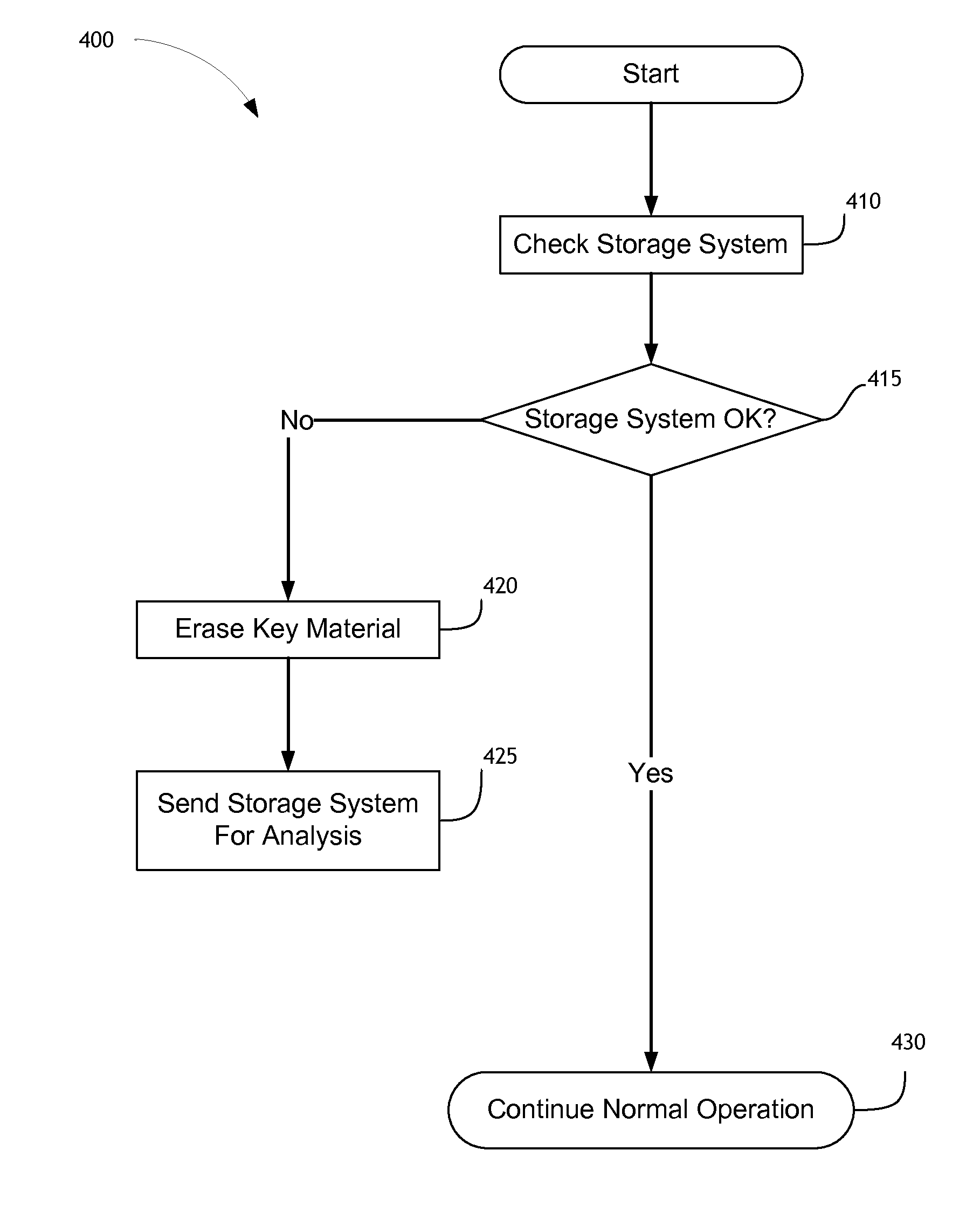
[0014]It is desirable to provide the ability to efficiently prevent access to sensitive data stored in a data storage system. Advantageously, a security mechanism is configured to prevent access without having to erase or modify (e.g., encrypt) data that is already stored in the data storage system. This is especially beneficial in a data center setting in which hundreds or more data storage systems are housed. The security mechanism is further configured to prevent access to data (or cryptographically erase data) in situations when the data storage system is rendered inoperable.
[0015]In some embodiments of the present invention, a security mechanism is configured so that previously encrypted data stored in the data storage system is left unmodified while an encryption key or information used to generate the key is erased or otherwise rendered inaccessible (e.g., performing a cryptographic erase). The security mechanism advantageously encrypts user data transparently to (e.g., without knowledge of) the host system so that encrypted data is stored on a storage medium. When stored data is retrieved, the security mechanism decrypts the data before it is provided to the host system. Further, the security mechanism is integrated with the data storage system. This can make tampering, hacking, or reverse engineering more difficult while providing an operator-friendly, efficient, quick, and easy to use mechanism of sanitizing the data storage system.
[0016]In some embodiments of the present invention, the security mechanism utilizes an encryption key which is stored in, or is generated from information stored in, a non-volatile memory module, such as a magnetoresistive random access memory (MRAM) module, integrated in the data storage system. Data stored in the MRAM module can be erased, written over, or otherwise rendered unrecoverable by exposing the MRAM module to a suitable electromagnetic field (e.g., magnetic field of a sufficient strength). For example, data stored in the MRAM module can be erased by degaussing, such as by using a degausser configured to erase data stored in magnetic media. As another example, the data storage system can comprise a magnetic field generator that can be activated (e.g., by supplying external power) to erase data stored in the MRAM module. Advantageously, by erasing data stored in the MRAM module, access to encrypted data stored in the data storage system can be prevented even in cases when the data storage system has failed or has otherwise been rendered inoperative or nonfunctional. Thus, some embodiments provide a method of preventing access that is very fast compared to other methods that physically erase all user data in storage devices, whose required time of operation has increased dramatically as data capacity per device has increased.
[0017]In some embodiments of the present invention, the data storage system is configured to erase from the MRAM module or otherwise render unrecoverable (e.g., written over) the encryption key or information from which the encryption key is generated. For example, this can be performed in response to a command (e.g., a vendor specific command that is not part of standard command interface between a host system and the data storage system) received from a host system. Once the key or information from which the key is generated is erased, encrypted data stored in the data storage system cannot be decrypted, and access is prevented. As a result, the data storage system is sanitized.
System Overview
[0018]FIG. 1A illustrates a combination 100A of a host system and a data storage system that implements MRAM-based security according to one embodiment of the invention. As is shown, the data storage system 120 (e.g., a hard disk drive, hybrid disk drive, solid-state drive, etc.) includes a controller 130 and a non-volatile memory array 150. The non-volatile memory array 150 comprises non-volatile memory, such as flash integrated circuits, Chalcogenide RAM (C-RAM), Phase Change Memory (PC-RAM or PRAM), Programmable Metallization Cell RAM (PMC-RAM or PMCm), Ovonic Unified Memory (OUM), Resistance RAM (RRAM), NAND memory (e.g., single-level cell (SLC) memory, multi-level cell (MLC) memory, or any combination thereof), NOR memory, EEPROM, Ferroelectric Memory (FeRAM), Magnetoresistive RAM (MRAM), other discrete NVM (non-volatile memory) chips, or any combination thereof. The data storage system 120 can further comprise other types of storage (not shown), such as one or more magnetic storage modules.
[0019]The controller 130 can be configured to receive data and/or storage access commands from a storage interface module 112 (e.g., a device driver) of a host system 110. Storage access commands communicated by the storage interface 112 can include write data and read data commands issued by the host system 110. Read and write commands can specify a logical address (e.g., LBA) used to access the data storage system 120. The controller 130 can execute the received commands in the non-volatile memory array 150 and/or other storage modules (not shown).
[0020]Data storage system 120 can store data communicated by the host system 110. In other words, the data storage system 120 can act as memory storage for the host system 110. To facilitate this function, the controller 130 can implement a logical interface. The logical interface can present to the host system 110 data storage system's memory as a set of logical addresses (e.g., contiguous address) where host data can be stored. Internally, the controller 130 can map logical addresses to various physical locations or addresses in the non-volatile memory array 150 and/or other storage modules.
[0021]The controller 130 includes a data protector module 132 that implements a security mechanism (e.g., MRAM-based security) for preventing access to data stored in the data storage system 120. The controller also comprises an MRAM module 160 where an encryption key or information used to generate the encryption key is stored. In order to prevent access to the data storage system 120, data stored in the MRAM module 160 can be erased either under control of the controller 130 and/or the data protector module 132 or by applying magnetic field to erase data stored in the MRAM module 160. In one embodiment, the magnetic field can be applied by a magnetic field generator 170 integrated within the data storage system 120. For example, an operator can apply external power to the magnetic field generator 170 (e.g., a coil or coils) whose power connectors or terminals are exposed for this purpose. In another embodiment, the magnetic field generator 170 is external to the data storage system 120 (e.g., a degausser).
[0022]FIG. 1B illustrates a combination 100B of a host system and a data storage system that implements MRAM-based security according to another embodiment of the invention. As is illustrated, the MRAM module 160 is positioned outside the controller 130, and is connected to the controller via an interface 162. For example, the MRAM module 160 can be positioned on the same printed circuit board (PCB) as the controller 130. Other components of the combination 100B are described above.
MRAM-Based Security
[0023]FIG. 2 is a flow diagram illustrating a process 200 of securely storing data according to one embodiment of the invention. The process 200 can be executed by the controller 130 and/or the data protector module 132. The process 200 starts in block 210 where it encrypts data received from the host system 110. This can be performed in response to receiving a write data command from the host system. In one embodiment, as is further explained below, the data is encrypted using a key (e.g., an encryption key) generated or derived from key data or material stored in the MRAM module 160. The encrypted data is stored in the data storage system 120 (e.g., in the non-volatile memory array 150) in block 215. In block 220, the process 200 retrieves the stored encrypted data and decrypts it using the encryption key. This can be performed in response to receiving a read data command from the host system 110. In block 225, the process 200 provides decrypted data to the host system. Accordingly, the process of securely storing data by encrypting or decrypting it is performed transparently to (e.g. without knowledge of) the host system 110. In another embodiment, key data comprises the encryption key itself.
[0024]FIG. 3 is a flow diagram illustrating a process 300 of initializing a data storage system 120 according to one embodiment of the invention. The process 300 can be executed by the controller 130 and/or the data protector module 132. The process 300 begins in block 305 when the data storage system 120 is initialized (e.g., powered up). In block 310, the process attempts to read key data or a record comprising key data (described below) stored in the MRAM module 160. In block 315, the process determines whether it successfully retrieved key data or the record comprising key data. In case key data (or the record) was successfully read, the process 300 transitions to block 335 where it generates an encryption key using key data. In one embodiment, the key is generated using a key derivation function (KDF) applied to key data and a randomly generated number (e.g., 1024 bits):
Key=KDF(key data,seed) (1)
[0025]The seed value in equation (1) is the random number, which functions as cryptographic salt in order to prevent lookup table assisted dictionary attacks and other hacking attempts. The random number can be unique to each data storage system 120. In one embodiment, the key is generated by applying a key derivation function to the randomly generated number as follows:
Key=KDF(random number) (2)
[0026]The key derivation function of equations (1) and/or (2) can be configured to be slow (e.g., undergo a number of iterations for generating the key) in order to prevent brute force attacks, dictionary attacks, and the like. In one embodiment, any suitable key derivation function can be used, such as KDF1, KDF2, KDF3, KDF4, password-based key derivation function (e.g., PBKDF2), message authentication code (MAC)-based key derivation function, hash-based message authentication code (HMAC)-based key derivation function, etc. In another embodiment, another suitable process for generating an authentication key can be used.
[0027]In one embodiment, key data can be protected by an error correction code (ECC) value configured to recover key data in case of memory errors. The ECC value is utilized by the ECC process to correct memory errors and recover key data. The ECC value can be stored in the MRAM module 160 or another storage module of the data storage system 120, such as the non-volatile memory array 150. In one embodiment, an authentication field can be used to protect the authenticity of key data. The authentication field can be derived or generated using a cryptographic hash function, such as SHA-2 and the like. The authentication field can be used to protect key data from a hacking attempt. For example, the following record comprising key data can be stored in the MRAM module 160:
struct security{key data;random number;ECC value;authentication value} (2)
[0028]In one embodiment, the key generated from key data, such as by using equations (1) or (2), can be a key encryption key used to access the encryption key stored in the data storage system 120 (e.g., in the non-volatile memory array 150), which is used for encrypting and decrypting data stored in the data storage system. In one embodiment, the encryption key itself can be stored in the MRAM module 160, and key data is not used. In one embodiment, the random number is used as key data for generation of the encryption key, such as by using equation (2).
[0029]In case key data or the record comprising key data was not successfully read, the process 300 transitions to block 320. Key data (or the record comprising key data) may not be accessible when the MRAM module 160 was not properly initialized, when data stored in the MRAM module was erased or overwritten, when the storage system has failed, etc. As is illustrated, the process generates a random number (e.g., 1024 bit random number) in block 320, which is used as cryptographic salt to generate the key using equation (1) or to directly generate the key using equation (2). In block 325, the process 300 regenerates the record (such as record (2)) by computing or deriving the ECC value and the authentication field. The process 300 transitions to block 330 where it stores the record in the MRAM module 160. The process 300 transitions to block 310 where the process again attempts to read key data or the record comprising key data. If the process 300 successfully retrieves key data or the record comprising key data, the process transitions to block 335. In block 335, the process 300 generates the encryption key using key data. In block 340, the process 300 initializes the controller 130, and normal operation is continued in block 345.
[0030]In one embodiment, if key data cannot be accessed or retrieved, the process 300 indicates (not shown) that the data storage system 120 cannot be properly initialized and that stored data is not accessible. In such case, the data storage system 120 may need to be reformatted and a new or replacement key data value may need to be stored in the MRAM module 160. In another embodiment, if key data cannot be accessed or retrieved, the process 300 can generate a replacement key data according to the rules used to generate key data, such as by generating a new random number used to generate a new or replacement key.
[0031]FIG. 4 is a flow diagram illustrating a process 400 for prevention of access to stored data (e.g., sanitization of the data storage system) according to one embodiment of the invention. The process 400 can be executed by the controller 130 and/or the data protector module 132. The process 400 begins in block 410 where it determines whether the data storage system 120 is operating normally. For example, following a system error (which may result in a reset of the data storage system 120), a hardware test can be performed, interrupts can be checked, memory test can be performed, and the like. If the process 400 determines that the data storage system 120 is operating normally, it transitions to block 430 where the data storage resumes regular operation. On the other hand, if the process 400 determines that the data storage system 120 is experiencing a severe error or has otherwise failed or became nonfunctional, the data storage system may have to be sent for repair or failure analysis. For example, the data storage system 120 may be sent to the manufacturer for fault analysis.
[0032]In one embodiment, the data storage system 120, should be secured or sanitized so that access to sensitive data is prevented. This should be performed before the storage system leaves a protected facility (e.g., a data center). When the data storage system 120 is operational, access can be prevented by erasing data stored in the MRAM module 160, in which the encryption key, key data or the record comprising key data is stored. Once the key or key data has been erased, stored data cannot be decrypted. However, when the data storage system 120 has failed or is otherwise rendered nonfunctional, data stored in the MRAM module 160 can be erased by applying magnetic field of sufficient strength to disrupt the recorded magnetic cells. In block 420, data stored in the MRAM module is erased or written over. In one embodiment, this can be accomplished by the operator applying external power to terminals of the magnetic field generator 170. In another embodiment, the operator can use a degausser, which utilizes a permanent magnet, electromagnet, etc. In yet another embodiment, access to data stored in the data storage system 120 can be prevented by erasing data stored in the MRAM module 160 using a permanent magnet. Once data stored in MRAM module 160 has been erased, the data storage system 120 has been sanitized. In one embodiment, the data storage system 120 can include a visual, audible, etc. indicator (e.g., an LED) for signaling to the operator that access to data stored in the data storage system has successfully been prevented.
[0033]In block 425, the sanitized data storage system 120 can be shipped from the protected facility for failure analysis, end of life disposal, transfer to another facility, and the like. In case the data storage system 120 has failed, it may be reused by fixing the problem that caused the failure, performing formatting of the storage module(s) (e.g., the non-volatile memory array), and regenerating key data or the record.
[0034]FIG. 5A illustrates a data storage system 500A that comprises an anti-tampering label 510 according to one embodiment of the invention. One of the ways to hack the data storage system in order to gain access to data stored in the data storage system is to forge the contents of the MRAM module 160 in order to obtain key data or the encryption key. In one embodiment, this can be prevented by placing the anti-tampering label 510 over the controller 130, which includes the MRAM module 160. The anti-tampering label 510 indicates whether the data storage system 500A, and particularly the MRAM module 510, has been tampered with. Existing regulations, such as Federal Information Processing Standards (FIPS) 140, require anti-tampering labels (e.g., label 510) to protect a cryptographic module.
[0035]In one embodiment, the anti-tampering label 510 is also configured as an electromagnetic (or RF) shield, which protects parts of the controller 130 from magnetic field that may be applied to erase data stored in the MRAM module 160. In another embodiment, a separate RF shield (not shown) can be integrated in order to protect components of the data storage system (e.g., magnetic storage modules, non-volatile memory array 150, etc.) from magnetic field.
[0036]FIG. 5B illustrates a data storage system 500B that comprises an anti-tampering label 520 according to another embodiment of the invention. Data storage system 500B comprises the controller 130 and the MRAM module 162 external to the controller. The MRAM module 160 is connected to the controller 130 by the interface 162. The anti-tampering label 520 is positioned over the MRAM module 160 and an interface 162 between the MRAM module 160 and the controller 130. The anti-tampering label 520 indicates whether the MRAM module 160 or the interface 162 have been tampered with.
Conclusion
[0037]Embodiments of secure data storage systems disclosed herein are configured to efficiently prevent access to stored data without having to erase or modify user data. Embodiments of secure data storage systems disclosed herein are further configured to prevent access when data storage systems are nonfunctional. In one embodiment, an encryption key and/or information used to generate the encryption key is stored in an MRAM module integrated within a data storage system. Data stored in the data storage system is encrypted using the encryption key. Encryption and decryption of data are performed transparently to a host system. The encryption key or information used to generate the encryption key can be erased or otherwise rendered inaccessible. In addition, if the data storage system has become nonfunctional, data stored in the MRAM module can be erased by application of magnetic field of a sufficient strength. Once the encryption key or information used to generate the encryption key has been erased, access to data stored in the data storage system is prevented, and the data storage system is sanitized.
Other Variations
[0038]Those skilled in the art will appreciate that in some embodiments, an encryption key can be stored or generated from information stored in various non-volatile memory modules, such as a smart card, Trusted Platform Module (TPM chip), EEPROM, and the like. Preventing access to data stored in the storage subsystem can be accomplished by destroying the smartcard, destroying the TPM chip, disabling power (e.g., external power) supplied to the EEPROM module, and the like. Additional system components can be utilized, and disclosed system components can be combined or omitted. The actual steps taken in the disclosed processes, such as the processes illustrated in FIGS. 2, 3, and 4, may differ from those shown in the figures. Depending on the embodiment, certain of the steps described above may be removed, others may be added. Accordingly, the scope of the present disclosure is intended to be defined only by reference to the appended claims.
[0039]While certain embodiments have been described, these embodiments have been presented by way of example only, and are not intended to limit the scope of the protection. Indeed, the novel methods and systems described herein may be embodied in a variety of other forms. Furthermore, various omissions, substitutions and changes in the form of the methods and systems described herein may be made without departing from the spirit of the protection. The accompanying claims and their equivalents are intended to cover such forms or modifications as would fall within the scope and spirit of the protection. For example, the systems and methods disclosed herein can be applied to hard disk drives, hybrid hard drives, and the like. In addition, other forms of storage (e.g., DRAM or SRAM, battery backed-up volatile DRAM or SRAM devices, EPROM, EEPROM memory, etc.) may additionally or alternatively be used. As another example, the various components illustrated in the figures may be implemented as software and/or firmware on a processor, ASIC/FPGA, or dedicated hardware. Also, the features and attributes of the specific embodiments disclosed above may be combined in different ways to form additional embodiments, all of which fall within the scope of the present disclosure. Although the present disclosure provides certain preferred embodiments and applications, other embodiments that are apparent to those of ordinary skill in the art, including embodiments which do not provide all of the features and advantages set forth herein, are also within the scope of this disclosure. Accordingly, the scope of the present disclosure is intended to be defined only by reference to the appended claims.
PUM


Description & Claims & Application Information
We can also present the details of the Description, Claims and Application information to help users get a comprehensive understanding of the technical details of the patent, such as background art, summary of invention, brief description of drawings, description of embodiments, and other original content. On the other hand, users can also determine the specific scope of protection of the technology through the list of claims; as well as understand the changes in the life cycle of the technology with the presentation of the patent timeline. Login to view more.