Cutting element

a cutting element and cutting plate technology, applied in the field of cutting plates, can solve the problems of unsupported, protruding lip forms, risk of unsupported lip fracturing,

Active Publication Date: 2014-12-16
NAT OILWELL VARCO LP
View PDF65 Cites 7 Cited by
  • Summary
  • Abstract
  • Description
  • Claims
  • Application Information

AI Technical Summary

Problems solved by technology

In use, the exposed, untreated part of the diamond layer tends to wear more quickly than the treated part with the result that an unsupported, protruding lip forms, and this effect is particularly apparent where the treated layer, i.e. that from which the binder catalyst is removed, forms only a relatively small proportion of the overall depth of the diamond layer.
In such arrangements, there is a risk of the unsupported lip fracturing.

Method used


Image

  • Cutting element
  • Cutting element
  • Cutting element

Examples


Embodiment Construction

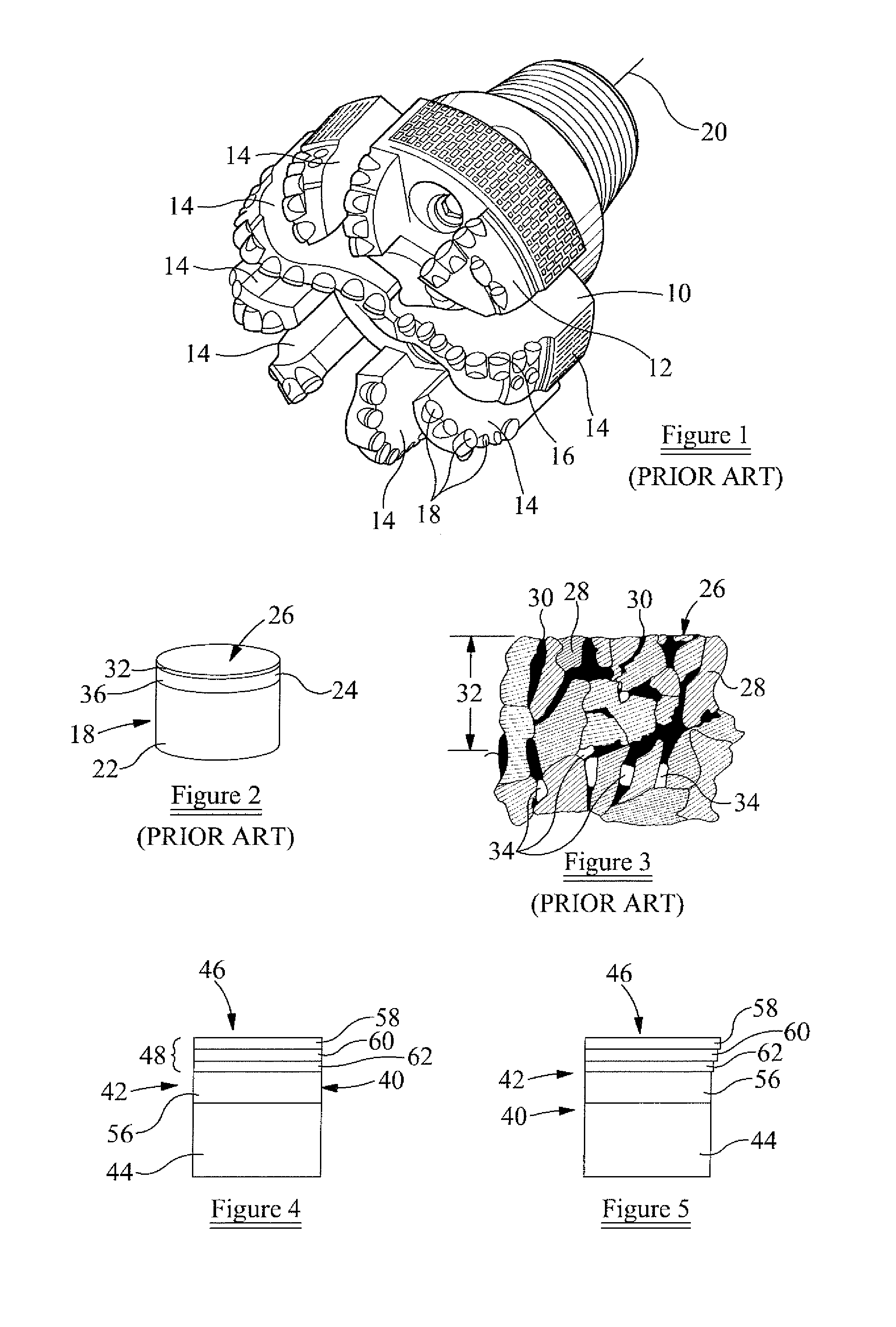
[0025]Referring firstly to FIG. 1 there is illustrated a drill bit comprising a bit body 12 formed with a plurality of outwardly extending blades 14. A front or leading edge 16 of each blade 14 carries a plurality of cutting elements 18. The cutting elements 18 are arranged such that, in use, rotation of the drill bit 10 about its axis 20 whilst an axially directed weight-on-bit loading is applied to the drill bit causes the cutting elements 18 to engage and bear against a formation, gouging, scraping, abrading or otherwise removing material from the formation, thereby extending a borehole being drilled using the drill bit 10.

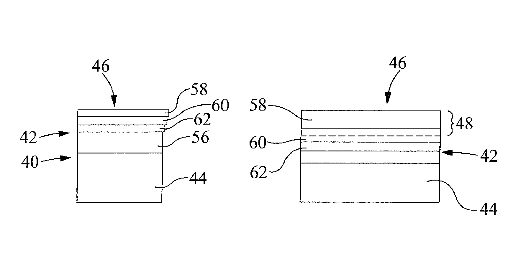
[0026]As shown in FIG. 2, each cutting element 18 comprises a substrate 22 to which is integrally bonded an element 24 of a superhard material. The superhard material is polycrystalline diamond, and the substrate 22 is of a less hard material, for example tungsten carbide.

[0027]The element 24 of polycrystalline diamond has an end working surface 26, and is made...


PUM

PropertyMeasurementUnit
thicknessaaaaaaaaaa
thicknessaaaaaaaaaa
thicknessaaaaaaaaaa

Abstract

A cutting element includes a multilayer polycrystalline diamond element bonded to a substrate of a less hard material. The polycrystalline diamond element defines a matrix of interstitial volumes. The interstitial volumes of a first region of the diamond layer are adjacent a working surface thereof being substantially free of a catalyzing material. The interstitial volumes of a second region of the diamond layer are remote from the working surface containing the catalyzing material.

Description

CROSS REFERENCE TO RELATED APPLICATIONS[0001]This application claims priority from GB Provisional Patent Application file No. 0901984.5 filed on Feb. 9, 2009, which is incorporated by reference herein for all it contains.BACKGROUND OF THE INVENTION[0002]1. Field of the Invention[0003]This invention relates to a cutting element and in particular a cutting element suitable for use on a drill bit for use in the formation of boreholes.[0004]2. Description of the Related Art[0005]One form of cutting element for use on a drill bit comprises a table of superhard material, for example polycrystalline diamond, which is bonded to a substrate of a less hard material, for example tungsten carbide. Cutting elements of this type are well known and are available in a range of shapes and sizes for use in a range of applications.[0006]This type of cutting element is manufactured using a high temperature, high pressure process in which a tungsten carbide substrate element, diamond powder and a binder...

Claims


Application Information

Patent Timeline
Patent Type & Authority Patents(United States)
IPC IPC(8): B22F7/06B22F5/00E21B10/567C22C26/00C22C29/08
CPCB22F2999/00B22F2207/03B22F7/06B22F2005/001E21B10/5676E21B10/567B22F2207/13C22C29/08C22C26/00E21B10/46E21B10/54E21B10/5735
Inventor GRIFFIN, NIGEL D.HUGHES, PETER R.
Owner NAT OILWELL VARCO LP
Why Eureka
Try Eureka