Stepped polycrystalline diamond compact insert

Inactive Publication Date: 2005-06-14
GEN ELECTRIC CAPITAL
View PDF22 Cites 100 Cited by
  • Summary
  • Abstract
  • Description
  • Claims
  • Application Information

AI Technical Summary

Benefits of technology

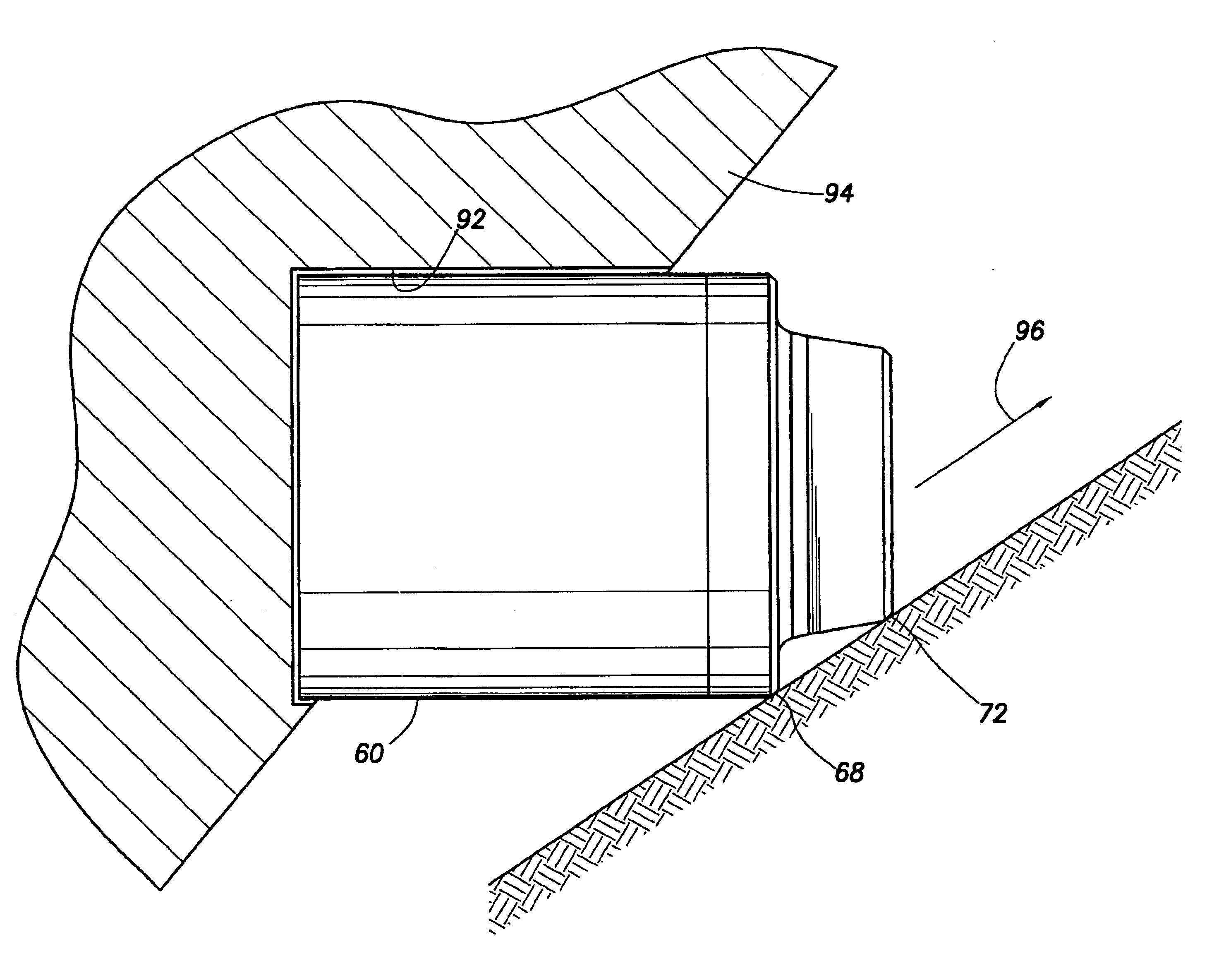
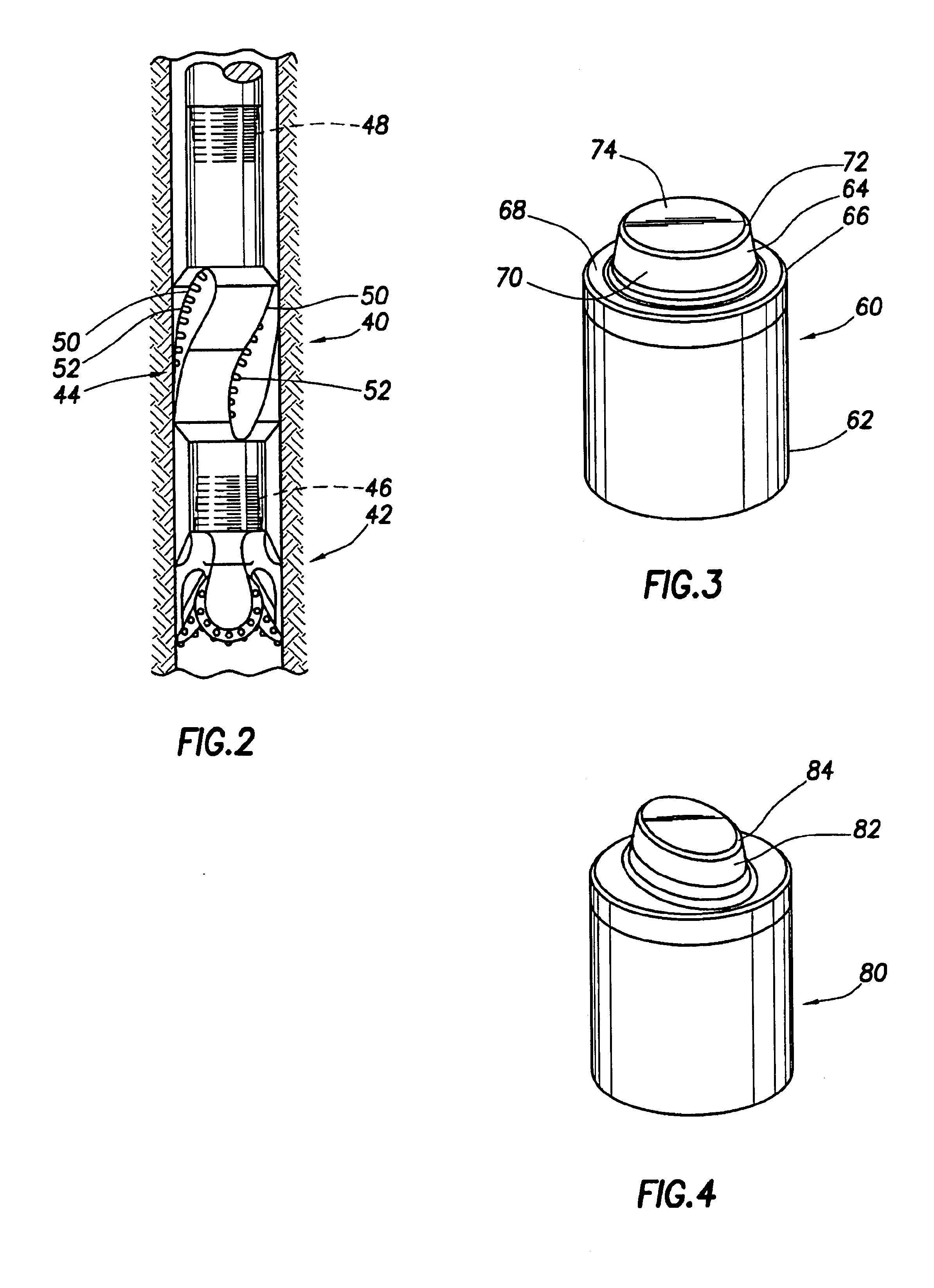
[0006]The present invention addresses both of these noted problems in the art by providing a PDC insert comprising a plug section and a pedestal section. The cutter insert is preferably formed of tungsten carbide, except for two exterior surfaces covered with PDC. The plug section may be circular or oval in cross section perpendicular to the axis of the insert. The plug section and the pedestal each defines a shoulder which is coated with a PDC layer. In one preferred embodiment of t

Problems solved by technology

This narrow groove reduces the rock strength of the formation cut by the plug surface and obviously reduces the amount of rock cut by the plug surface.
As the inserts embed deeper, work load is increased and this results in more torque being required to turn the bit.
As previously described, at som

Method used


Image

  • Stepped polycrystalline diamond compact insert
  • Stepped polycrystalline diamond compact insert
  • Stepped polycrystalline diamond compact insert

Examples


Embodiment Construction

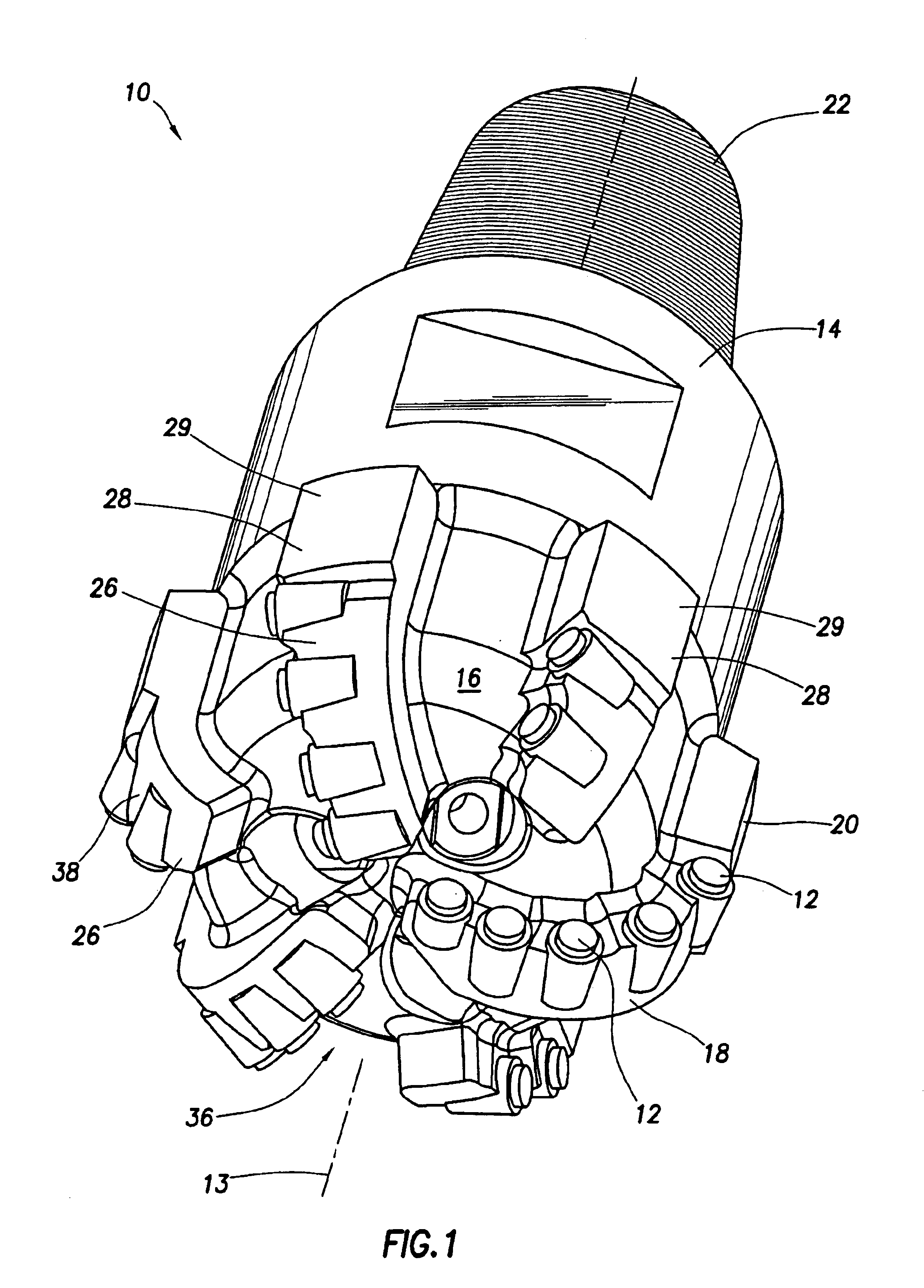
[0019]FIG. 1 shows a fixed cutter drill bit 10 including inserts 12 of the present invention. The drill bit 10 has a central axis of rotation 12 and a bit body 14 having a leading face 16, an end face 18, a gauge region 20, and a shank 22 for connection to a drill string (not shown). A plurality of blades 26 extend from the leading face 16 of the bit body away from the central axis of rotation 12 of the bit 10. Each blade 26 terminates in a gauge pad 28 having a gauge surface 29 which faces a wall 30 of a borehole (not shown).

[0020]A number of cutter inserts 12 are mounted on the blades 26 at the end face 18 of the bit 10 in both a cone region 36 and a shoulder region 38 of the end face 18. Each cutter 12 partially protrudes from its respective blade 26 and the cutter inserts are spaced apart along the blade 26, typically in a given manner to produce a particular type of cutting pattern. The structure of the cutter insert of the invention is shown in greater detail in FIGS. 3, 4, an...


PUM


Abstract

The present invention addresses this need in the art by providing a cutter insert comprising a plug section and a cutter pedestal. The cutter insert is preferably formed of tungsten carbide, except for two exterior surfaces covered with PDC. The plug section may be circular or oval in cross section perpendicular to the axis of the insert. The plug section and the pedestal each defines a shoulder which is coated with a PDC layer. In this way, two cutting surfaces are applied to the formation, enhancing the cutting ability of the insert.

Description

FIELD OF THE INVENTION[0001]Th present invention relates generally to earth boring drill bits, and in particular to a polycrystalline diamond compact (PDC) insert exhibiting a stepped profile structure for use in an fixed cutter earth boring bit or reamer.BACKGROUND OF THE INVENTION[0002]PDC inserts are commonly used to increase the wear resistance of surfaces in certain types of down hole tools. For example, inserts on a reamer, in association with a drill bit, are used on outer blade surfaces to resist wear from the borehole wall. The reamer enlarges the bore hole to a diameter than that created by the drill bit.[0003]The function of the reamer is to maintain the diameter of the hole as the drill bit proceeds downwardly through the rock formation. As the bore hole is being drilled, the rock drill bit gradually wears to undersize and thus the hole which is cut gradually becomes of undersize diameter. The function of the reamer, which typically has PDC inserts along the outer blade ...

Claims


Application Information

Patent Timeline
IPC IPC(8): E21B10/46E21B10/56E21B10/567E21B10/573
CPCE21B10/5735E21B10/5673
Inventor ESTES, ROY D.CASTLE, JACK
Owner GEN ELECTRIC CAPITAL
Why Eureka
Try Eureka